Optical Scientific Inc
OFS 2000CW User’s Guide
P/N 1910-905
Rev. 03/28/13
11
2 Pre
– Installation
2.1 OFS Placement
Since air flow has the characteristics of a fluid, the best location for any flow sensor is always at the place
where the flow profile is well developed and consistent. A certain amount of leading and trailing distance
(usually defined in “pipe diameters”) from bends or flow disturbances in the pipe or stack is necessary for
stabilization. Most types of flow sensors need very long straight distances to achieve a steady near-laminar
flow. The common sensor sees turbulence as an error which needs to be eliminated. For OFS, turbulence is
desirable. It is always easier to add turbulence than to eliminate it . Because the OFS light beam passes
through the entire flow cross-section, it can tolerate much shorter linear length, where other instruments may
require ten times the distance or more before they can become effective.
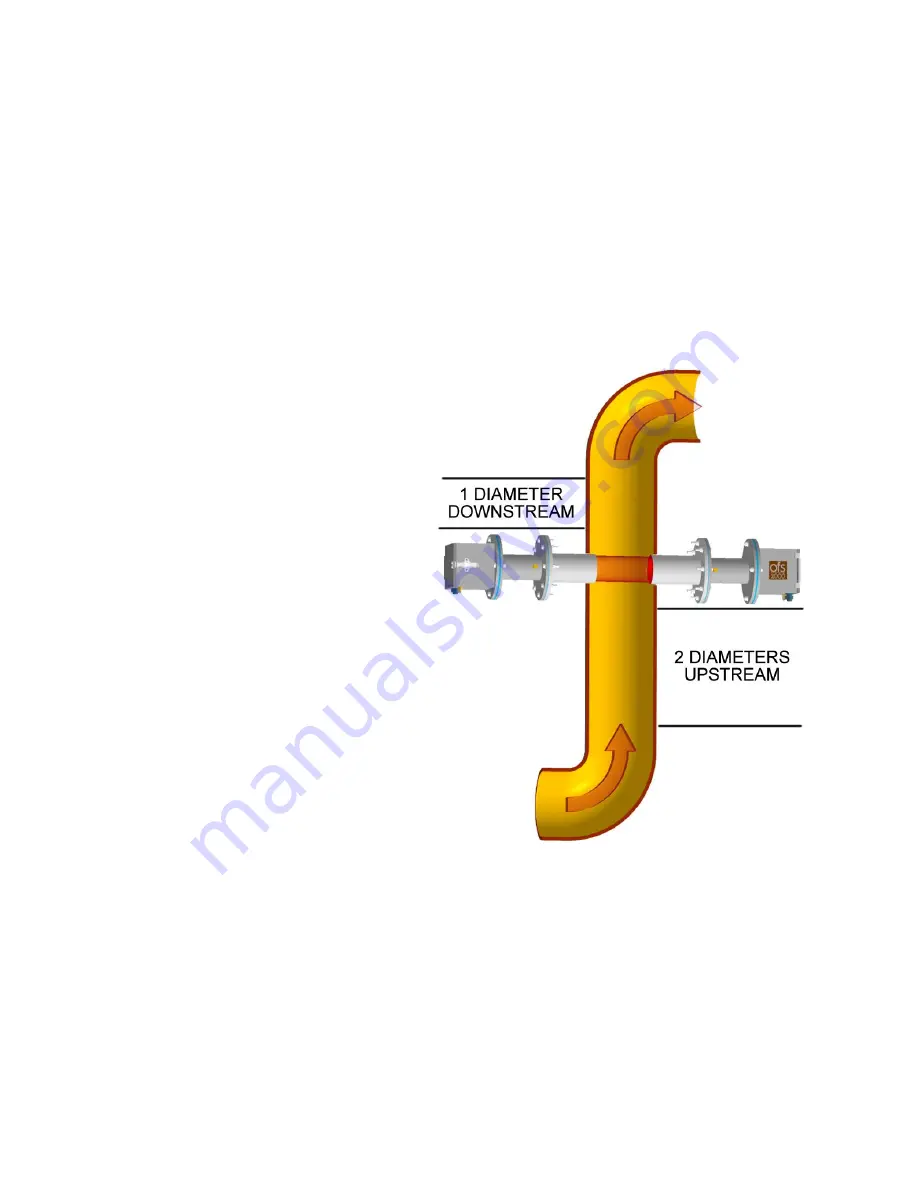
Usually linear lengths more than two
times the pipe diameter leading
(upstream of the OFS) and one times the
pipe diameter trailing are good enough
for OFS to make a representative flow
measurement. In some cases, OFS 2000
units have been installed right at the
elbow of a pipe and still provided
satisfactory measurements. Consult OSI
if you have any placement concerns.
Application requirements may require
differing arrangements from the standard
stack or duct. The shape, diameter, or
cross section must also be taken into
consideration. In some cases two OFS
systems have been used in an “X”
configuration to measure a large stack.
In others, they have been mounted
diagonally to measure across a
rectangular duct corner-to-corner. The
OFS will measure at any distance from
0.15 to 10 meters. Other distances are
possible. Again consult OSI if you have
questions regarding proper placement.
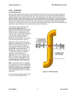
Note:
In cases like these, it is advisable
to mount the units so that the light beam
is aligned along the axis of the upstream
bend. This ensures that any stratification
in the developed flow pattern will pass
through the light beam and not slip by on
either side.
The Transmitter should be placed on the
inside curve of the upstream bend
Figure 2.1 OFS Placement

