Optical Scientific Inc
OFS 2000CW User’s Guide
P/N 1910-905
Rev. 03/28/13
12
2.2 OFS 2000CW Sensor Placement
In addition to the general placement considerations described in the previous section, proper allowance must
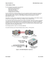
be made for the location of the Temperature Probe [1910-852] and Activator Heater [1910-850].
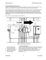
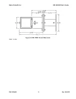
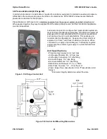
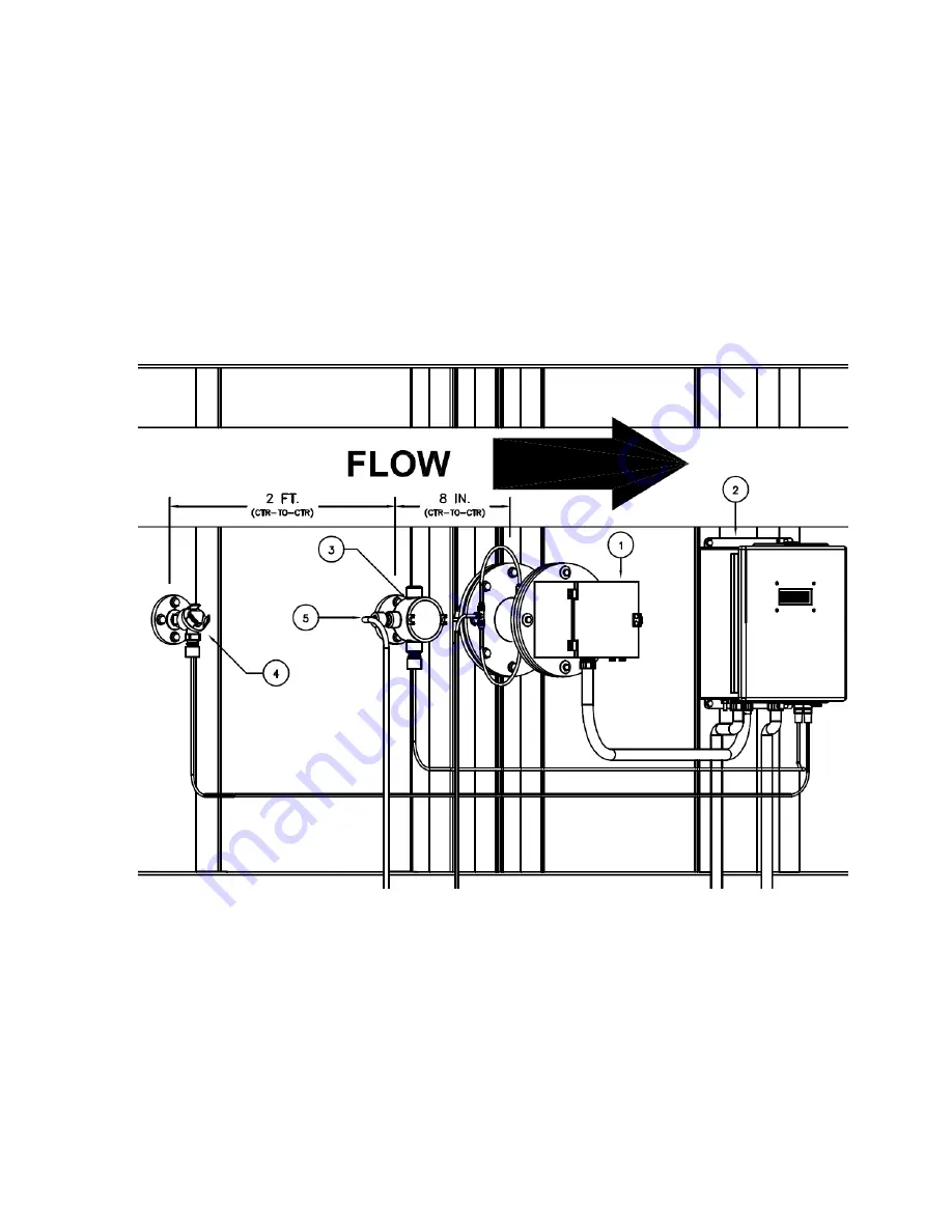
These are placed upstream of the light beam axis as shown in Figure 2.2 below. The heater and temperature
probe are aligned on the centerline and installed on the receiver side of the duct. The heater should be
mounted 8” upstream from the TX/RX light beam axis, and the temperature probe should be mounted 24 “
upstream from the heater. A certain amount of shifting may be allowed for as not all sites are ideal, but the
critical parameter is the 8” centerline distance between the heater and the light path. This should be adhered
to at minimum.
Figure 2.2 shows a typical installation in a horizontal duct.
Figure 2.2 Typical Sensor Placement
Component Description
Transmitter (not shown)
Mounted on opposite side and centered on common axis with receiver
1
Receiver Unit [1910-200]
Centered on axis with transmitter (see Flange Alignment in Section 2)
2
Control Unit [1910-302-1]
Contains DSP/Sensor and Customer Interfaces, Display
3
Activator Heater [1910-850]
Mounts in 3/4” NPT fitting at least 8” upstream on center with RX
4
Temp Probe [1910-852]
Mounts in 1/2” NPT fitting at least 24” upstream from heater
5
Heater AC Supply
Dedicated AC Line

