Optical Scientific Inc
OFS 2000CW User’s Guide
P/N 1910-905
Rev. 03/28/13
29
3.8 User Interface Connections
The OFS has two communication modes:
Analog
4-20mA Current Loop Outputs
Fault Relay & Cal Relay
External Cal Switch
Digital
RS-232 Serial Data Output
Control Interface
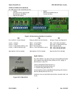
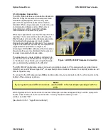
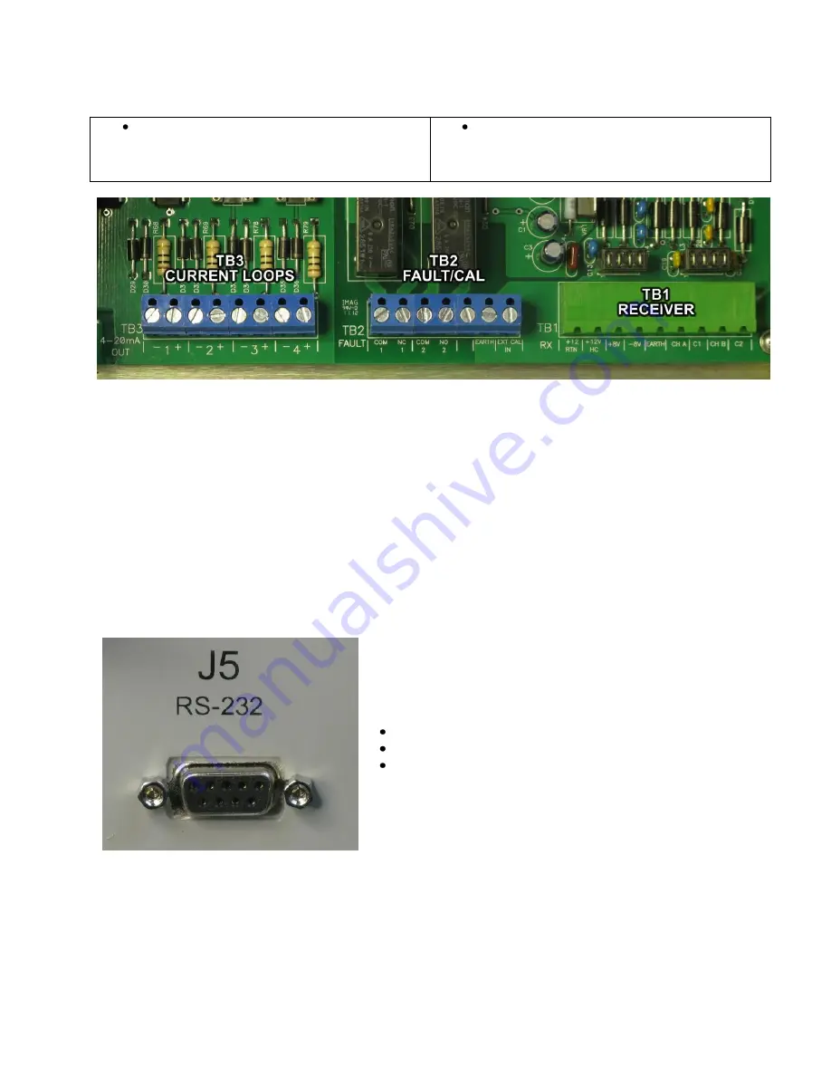
Figure 3.20 User Analog Interface Connections
TB3
TB2
TB1
Four 4-20 mA Current Outputs
Loop 1
– Velocity
Loop 2 - Volume
Loop 3
– Temperature (factory opt.)
Loop 4
– Pressure (factory opt)
[See Section 3.12 for details]
Relay and External Cal Contacts
TB2 1
– 2 Fault Relay
TB2 3
– 4 Cal Relay
TB2 5 No Connection
TB2 6
– 7 Ext Cal Switch connect.
[See Section 3.13 for details]
Receiver Power and Signal I/O
TB1 -1 & 2 12V & rtn f/heater
TB1 3 & 4 +8/-8VDC RX power
TB1 5 Signal Ground
TB1 6 & 7 Channel A Signal
TB1 8 & 9 Channel B Signal
[See Section 3.9 for details]
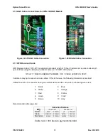
Digital Interface
The OFS 200CW is accessed through a female DB9 serial data
port located at the bottom of the enclosure. A PC, laptop, or
similar device is used for:
Setup configuration [See Section 4.1]
Flow data monitoring [See Section 5]
Troubleshooting [See Section 11]
Communications can be established through HyperTerminal or
similar software [See Section 3.14]
A screw-on cover is provided to protect the connector when not
in use.
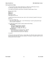
Figure 3.21 J5 Serial Port

