Optical Scientific Inc
OFS 2000CW User’s Guide
P/N 1910-905
Rev. 03/28/13
iv
Table of Figures
Figure 1.1 OFS 2000CW Basic Components .................................................................................................. 1
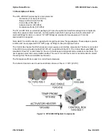
Figure 1.2 OFS 2000CW System Components ............................................................................................... 4
Figure 1.3 OFS 2000CW Transmitter .............................................................................................................. 5
Figure 1.4 OFS 2000CW Receiver .................................................................................................................. 6
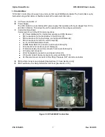
Figure 1.5 OFS 2000CW Control Box ............................................................................................................. 7
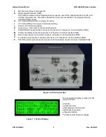
Figure 1.6 OFS Control Box ............................................................................................................................ 8
Figure 1.7 Control Display .............................................................................................................................. 8
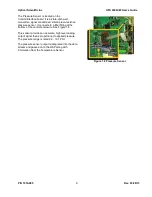
Figure 1.8 Pressure Sensor ............................................................................................................................ 9
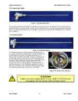
Figure 1.9 Temperature Probe .......................................................................................................................10
Figure 1.10 Activator Heater ..........................................................................................................................10
Figure 1.11 Heater Current Sensor ................................................................................................................10
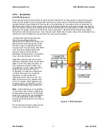
Figure 2.1 OFS Placement ............................................................................................................................11
Figure 2.2 Typical Sensor Placement .............................................................................................................12
Figure 2.3 Flange Installation (cutaway) .........................................................................................................13
Figure 2.4 Measured Flow Cross Section .......................................................................................................15
Figure 2.5 Flange Installation - Incorrect ........................................................................................................16
Figure 2.6 Flange Installation - Correct ..........................................................................................................16
Figure 2.7 Common Flange Dimensions ........................................................................................................16
Figure 3.1 Common Vertical Installation .........................................................................................................18
Figure 3.2 Common Horizontal Installation .....................................................................................................18
Figure 3.3 OFS Mounting Hardware...............................................................................................................18
Figure 3.4 OFS TX/RX Overall Dimensions....................................................................................................19
Figure 3.5 Control Box Mounting Dimensions ................................................................................................20
Figure 3.6 Purge Air Detail .............................................................................................................................21
Figure 3.7 Rotameter (flow meter) .................................................................................................................21
Figure 3.8 "Natural" Air Purge ........................................................................................................................21
Figure 3.9 Compressed Air Purge ..................................................................................................................21
Figure 3.10 Purge Air at 90° to Vertical Flow ..................................................................................................22
Figure 3.11 Rotameter Installation .................................................................................................................22
Figure 3.12 Typical Gate Valve Installation ....................................................................................................23
Figure 3.13 Z-Purge Control Unit ...................................................................................................................24
Figure 3.14 Control Unit Mounting Dimensions ..............................................................................................24
Figure 3.15 Typical Z-Purge Control Unit .......................................................................................................25
Figure 3.16 TX/RX Z-Purge Arrangement ......................................................................................................25
Figure 3.17 Control Box Z-Purge Arrangement ..............................................................................................26
Figure 3.18 Transmitter AC Connections .......................................................................................................28
Figure 3.19 Control Box AC Connections .......................................................................................................28
Figure 3.20 User Analog Interface Connections .............................................................................................29
Figure 3.21 J5 Serial Port ..............................................................................................................................29
Figure 3.22 OFS2000CW Interconnects ........................................................................................................30
Figure 3.23 Receiver Cable Connections .......................................................................................................30
Figure 3.24 TX AGC Cable Connection..........................................................................................................31
Figure 3.25 RX AGC Cable Connection .........................................................................................................31
Figure 3.26 TB3 Connections ........................................................................................................................33
Figure 3.27 Terminal Block 2 .........................................................................................................................34
Figure 3.28 OFS 200CW Computer Connection .............................................................................................35
Figure 4.1 HyperTerminal Open .....................................................................................................................37
Figure 4.2 "V" Poll Output ..............................................................................................................................37
Figure 4.3 Units of Measure ...........................................................................................................................37
Figure 4.4 Setup: Time Constant ...................................................................................................................38
Figure 4.5 Serial Output .................................................................................................................................38
Figure 4.6 Current Loop 1 ..............................................................................................................................38
Figure 4.7 Current Loop Assignments ............................................................................................................39
Figure 4.8 Correction Factor Entry .................................................................................................................39
Figure 4.9 Curve Fitting Setup .......................................................................................................................40
Figure 4.10 Curve Fitting Point Entry .............................................................................................................40


