Optical Scientific Inc
OFS 2000CW User’s Guide
P/N 1910-905
Rev. 03/28/13
47
7 Optical Alignment
How well the details of the receiver board and detectors can be seen during aiming depends on several factors
such as distance, the amount of mist or particulate in the gas stream, the amount of ambient light. These can
combine to make it difficult to see where the
“spot” of red light strikes the receiver. With proper care and
attention to details as described here, difficulties can be minimized if not eliminated.
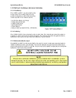
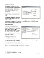
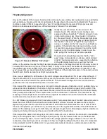
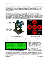
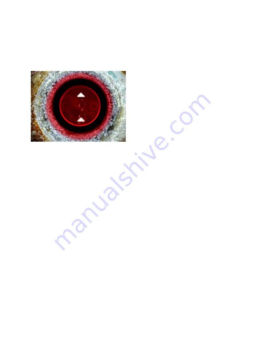
Ideally the user should see the two lenses on the
detector board. (The detector lens mounting is also
equipped with two Scotchlite™ reflector arrows for help
in determining proper aim. [See Figure 6.5 in Section
6.2
“Receiver Setup”]. When the transmitted light beam
shines on the detector lenses, they will reflect and look
like two little “cat’s eyes” at night. The key to proper
aiming is to make sure the “cat’s eyes” are as bright as
possible. If the detector board is clearly visible, you do
not need to measure any voltages or look at the A & B
readouts on the Controller display in order to aim the
LED, just get the “cat’s eyes” as red as possible.
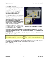
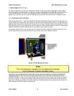
One problem that might be present is that the “cat’s
eyes” image is obscured by an intense central red spot
of light. This intense red spot is caused by the reflection
of the LED directly back to your eye from the front
surface of the window. Usually this bright red spot is somewhere in the target area but not in the very center (it
is usually off to the side or up in one of the corners). It is only in the center if the heads are mounted so that
the windows are exactly parallel. If this is the case, it will most likely block the detector lens reflection (“cat’s
eyes” image) that you would normally be looking for. Therefore, if the a bright red spot is in the center, just aim
the LED such that the red spot is as bright red as possible.
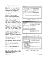
Once you are satisfied the LED is aimed, the A & B voltages should be within 30% of each other although. If
they are not within 30%, re-
do the aim until they are. By convention, the A detector is the one that first “sees”
the turbulence and is therefore the upstream detector. If the A detector voltage is too low then the beam is
pointed too far in the downstream direction, and vice-versa.
If the image of the detectors (cat’s eyes) is too hard to discern because of distance or mist / particles then you
will need electronic feedback of the amount of light received by the detectors to properly aim the LED. If the
Controller is mounted close by you can have someone call out the A and B values from the Controller display
while you adjust the LED aim. The A and B scales on the controller are 0-9.99 volts. The instrument is very
accepting in terms of light levels and will function anywhere in between 0.2 and 9.99 volts but the LED beam
must be aimed and centered on the detector board.
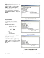
For
–CW Models (equipped with AGC transmitter control): Temporarily disconnect the AGC cable white wire to
break the circuit. Without the AGC cable connected the LED is driven to maximum power so there may be
segment as you pan the aim up and down and side to side where the A & B values max out at 9.99. If this is
the case, with practice, you will have to try and stop the pan in the approximate middle of this 9.99 maximum
plateau. If the readings never get to 9.99, then your job is just to get the A & B readings as high as possible (to
a maximum of about 8.0) and get the values of A & B within 30% of each other.
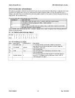
If the image of the detectors (cat’s eyes) is too hard to make out, and, in addition, the controller is inaccessible,
then you can bring back the C1 and C2 signals (and ground) from the receiver head over to the transmitter
head in a temporary cable. You can then measure the voltage potential using a voltmeter on the C1 and C2
conductors, compared to ground, as a measure of how much light is getting to the other side. C1 corresponds
to the A detector and C2 the B detector. For your temporary cable terminations, just slip conductors into the
Continued on next page
Figure 7.1 Receiver Window "Cat
’s Eyes"


