Optical Scientific Inc
OFS 2000CW User’s Guide
P/N 1910-905
Rev. 03/28/13
50
7. Optical Alignment
(Continued)
The A & B voltages do not have to be identical for the OFS to operate correctly. Generally, A & B voltages
should be within a maximum of 30% of each other. Velocity measurement is not dependent on the amplitude
of the A & B channels. .The OFS is very accepting in terms of light levels and will function anywhere in
between 0.2 and 9.99 volts, as long as the LED beam has been aimed and centered on the detector board.
7.1.1 Avoiding Receiver Saturation
As mentioned in Section. 7, the AGC cable should be temporarily disconnected during the aiming process so
that the transmitter output will be at a constant level and the A & B voltage levels will be true measurements. A
disadvantage to this practice is that at close range this may result in saturation of the photodetectors. This will
NOT cause any harm to any components
– but will cause the A & B voltage readings to “max out” and make it
difficult to determine when the light beam is truly centered on the receiver module.
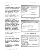
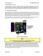
A temporary remedy for this is to insert a sheet of neutral density filter material in the Receiver interior in the
space between the Receiver Module A & B Lenses and the inside of the Receiver Window.
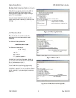
Figure 7.5 Filter Material Insertion
Note:
This is a temporary measure only for alignment purposes.
Not to be used in actual operating mode.
Since this is only a measurement of relative light intensity any neutral (gray) color flexible semitransparent
material will work. We have found that the smoky plastic sheet used in anti-static packaging of electronic
components does very well, and can easily be layered to increase density if needed. Insert a layer (or layers)
as shown in Figure 7.5 until A & B readings reach workable levels. Adjust the Transmitter aim as described
previously until optimum alignment is reached. Remove the filter material and re-connect the AGC cable. The
OFS will adjust transmitter output to proper levels

