Optical Scientific Inc
OFS 2000CW User’s Guide
P/N 1910-905
Rev. 03/28/13
51
8 Correlation
The Correlati
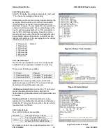
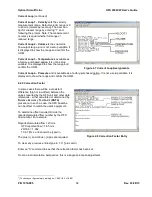
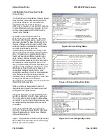
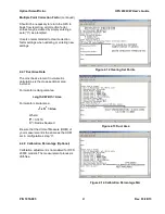
on output (“Corr”) on the display as shown in Figure 7.4 is a very important diagnostic indicator.
The Receiver photodetectors measure scintillation, which is the variation of light caused by it’s passage
through pockets of air with different temperature and density. With OFS 2000CW, the pockets of air are
moving through the fixed LED beam are the natural turbulence eddies in the flowing air. The light detectors are
aligned with the flow so that the A detector “sees” the eddies first, then the B detector “sees” them. The two
detectors are close enough to each other that the eddies do not have time to be destroyed, i.e., the same
eddies pass in front of the A detector, and the B detector. The scintillation signal recorded by the A detector is
a unique “fingerprint” of those eddies. When that same set of eddies then passes in front of the downstream B
detector, the scintillation “fingerprint” will have the same shape.
The computer then essentially starts a stopwatch when it first sees the fingerprint in the A detector and then
stops the stopwatch when it sees the same fingerprint in the B detector. It then knows how much time it has
taken for a specific set of eddies to move the fixed distance that separates the detectors. From this time and
distance knowledge, it can calculate and report the velocity of the moving air. This measurement is continuous
and uninterrupted.
The correlation output is a unitless number in the range of 0 to 999. It is the measure of how well the
fingerprint shapes correlate in terms of shape in the most recent information from the A and B detectors. By
extensive field experience it has been determined that when the correlation number is consistently over 100
the fingerprint match is good enough that we can be confident it was made by the same set of eddies and the
velocity output will be within specifications.
Various factors may affect the shape match of the scintillation fingerprints and therefore the correlation output.
Strong signals with high correlation numbers are relatively immune, but one factor should be mentioned for the
sake of thoroughness. This most significant detractor is “noise”. This is not electronic noise per se, but
physical or optical noise which then affects the signal with much the same result as the electronic variety.
In most installations the total noise signal is proportionately small compared to the scintillation signal and
contributes very little to the overall signal pattern that is being compared between the A and B detectors.
However, if, for example, the scintillation signal is weak (the gases are cold and laminar) and/or the noise
signals are strong (say there is high electrical noise, mechanical vibration, or conflicting air turbulence flows in
the image), then the overall signal pattern will no longer be dominated by the scintillation signal from the flow
eddies. In this case it may be that the A shape and B shape will no longer match and cause correlation to
degrade. However, this condition can be overcome.
The OFS 2000CW is designed to operate properly in a wide range of conditions. Following the instructions in
this User’s Guide, and other OSI application notes, should result in a non-problematic, well-functioning system.
If your correlation number does NOT remain over 100, the condition may be remedied without extreme
measures. Discussion of specifics at this point is not within the scope of this manual. Contact OSI for
assistance in correcting this condition.
If you find your Corr output is low, it is wise to continuously record the RS-232 output [See Section 5
“Poll
Commands and Data Output
”] so the data collected has all the diagnostics and output information available
such that the problem can be analyzed, diagnosed and solved.


