Optical Scientific Inc
OFS 2000CW User’s Guide
P/N 1910-905
Rev. 03/28/13
v
Figure 4.11 Curve Fitting Entry Check ...........................................................................................................40
Figure 4.12 Clearing Set Points .....................................................................................................................41
Figure 4.13 Duct Area....................................................................................................................................41
Figure 4.14 Calibration Percentage N/A .........................................................................................................41
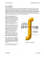
Figure 6.1 OFS 2000CW TX Module ..............................................................................................................45
Figure 6.2 OFS 2000CW RX Window ............................................................................................................45
Figure 6.3 Centering Light Beam ...................................................................................................................45
Figure 6.4 TX Rear View................................................................................................................................45
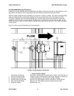
Figure 6.5 Receiver "A" & "B" Lenses ............................................................................................................46
Figure 6.6 Receiver LEDs and Flow Direction ................................................................................................46
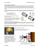
Figure 7.1 Receiver Window "Cat’s Eyes" ......................................................................................................47
Figure 7.2 Transmitter Module .......................................................................................................................48
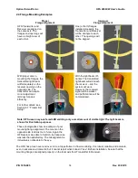
Figure 7.3 Beam Centering ............................................................................................................................48
Figure 7.4 Front Panel Display (example) .....................................................................................................48
Figure 7.5 Filter Material Insertion ..................................................................................................................50
Figure 9.1 Transmitter LEDs ..........................................................................................................................52
Figure 9.2 Receiver LEDs ..............................................................................................................................52
Figure 9.3 Control Enclosure Display .............................................................................................................53
Figure 9.4 Control & DSP Indicator LED's ......................................................................................................53
Figure 10.1 Window Cleaning ........................................................................................................................55
Figure 11.1 DSP Indicators ............................................................................................................................57
Figure 11.2 Control/Interface LEDs ................................................................................................................57


