Optical Scientific Inc
OFS 2000CW User’s Guide
P/N 1910-905
Rev. 03/28/13
57
11.2 Control Enclosure Troubleshooting
There are no user-serviceable parts in the Control enclosure. Information provided herein may be helpful when
contacting OSI Technical Support.
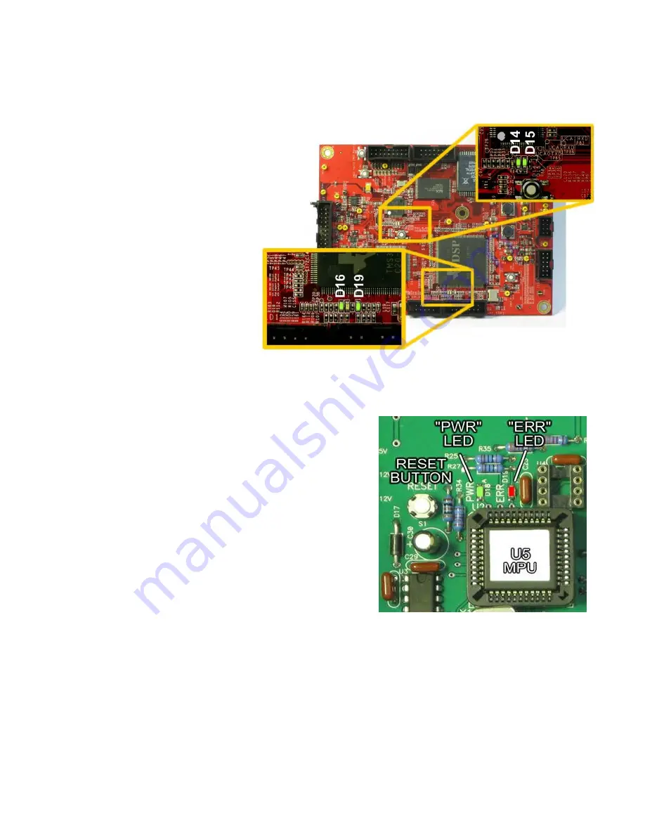
The Control/Interface Board and
DSP (Digital Signal Processing)
board have indicator LED’s which
will show PCB activity and may
help in isolating faults
11.2.1 DSP lndicator LEDs
A quick look at the 4 indicating
LEDs will show any problems.
D14 lit and pulsing [LED0]
D15 lit and steady [LED1]
D16 lit and steady [GP12]
D19 lit and steady [GP15]
If any of the LED's aren't lit, check
the power outputs at the system
DC power supply. If the power
supply voltages are good, check
that all the cables are firmly
seated.
11.2.2 Control/Interface
Indicators
If the system “freezes” or “locks up” or will not respond to the
“V” or “R” poll characters, check the “PWR” (Power) and
“ERR” (Error) LEDs on the Control/Interface Board.
If the PWR LED is not lit, check the AC Line Voltage and the
DC power supply output
voltages. If the “ERR” LED is lit,
press and hold the nearby “RESET” button.
11.3 Transmitter Troubleshooting
11.3.1 Transmitter "Power" Led Not Lit
Check the AC voltage at the transmitter PCB terminal block. If
there is AC voltage present. replace the transmitter board. If
there is no AC voltage present, check the AC supply line for
fault.
11.3.2 Transmitter "Signal" Led Not Lit
Be sure the transmitter module wiring is firmly connected.
Replace the transmitter module.
Replace the transmitter PCB.
11.4 Receiver Troubleshooting
11.4.1 Receiver "Power" Led Not Lit
Check the +/- 8VDC voltages at the receiver PCB terminal block. If there is voltage present. Replace the
receiver PCB. If there is no DC voltage present, check the DC supply line for fault.
Figure 11.1 DSP Indicators
Figure 11.2 Control/Interface LEDs

