Optical Scientific Inc
OFS 2000CW User’s Guide
P/N 1910-905
Rev. 03/28/13
61
13 Technical Support
OSI Technical Support
techsupport@opticalscientific.com
Tel: 301 963 3630 xt 216
Fax: 301 948 4670
9AM
– 5PM Eastern Time Monday – Friday (except national holidays)
Telephone assistance for overseas customers is available by appointment.
E-mail at least 1 business day in advance.
Before Calling Technical Support:
Please have or be able to provide:
Unit or system model designation
:OFS 2000
–F/-CW/-V, etc.)
Unit or system serial number
Details of site and installation
(stack diameter, purge air, application, location, etc.)
Your name, phone number, and e-mail address
The more information you can provide
– the better we can help you.
Also you may wish to briefly review the topics listed below:
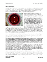
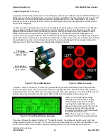
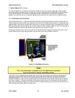
Check Transmitter and Receiver Alignment
It is possible that during periodic cleaning or maintenance of the TX and RX Units the
alignment can be disturbed. In a well - aligned installation the effect of movement is
negligible. In a marginally aligned installation, this can affect transmission and reception of
the light beam. [See Section 2.3
“Flange Alignment Guidelines”]
Understanding what the A & B numbers mean:
A and B channel voltages are simply indicators of the strength of the received light beam.
The A & B range is 1-9.9 volts. They do not have to be identical. They can vary up and
down with conditions in the flow. OFS will report reliably anywhere within that range. Signal
strength does not relate to accuracy of measurement.
The conditions to avoid are: signal saturation, and loss of signal, both of which will be
indicated by “signal out of range” message on the Control Panel display. These conditions
can be caused by a number of factors, such as misalignment, excess output from the
Transmitter, blockage of the light beam, and others readily imagined.

