7
3.4 Requirements for installation location and positioning
!
CAUTION
!
The product should be fitted in accordance with Part G3 of building regulations.
Liability for consequential damage will only apply if this is followed.
!
The safety valve supplied must be mounted on the cold water supply to the boiler. See
section 3.5.2.
!
The product should be placed in a dry and permanently frost-free position.
!
The product should be mounted on a wall suitable for the total weight of the product in operation.
!
If the product is fitted horizontally, the pipe connectors must point straight up.
It is
recommended that the product be screwed tight to the wall or a suitable surface regard-
less of the method chosen; use the screw holes (D).
If the product is fitted vertically, the electric box must face upwards. See page 8.
!
The product should be mounted to allow access to the junction box when needed. Mains cable
can be placed in the finished channels in the back of the product. Mains cable for wall socket
should be laid where it is not exposed to harmful contact.
!
The product should be easily accessible in the home for servicing and maintenance.
IMPORTANT: If the insulation is not correctly and
completely fitted, the product will not achieve
the specified ErP energy rating. The energy con-
sumption of the product could increase.
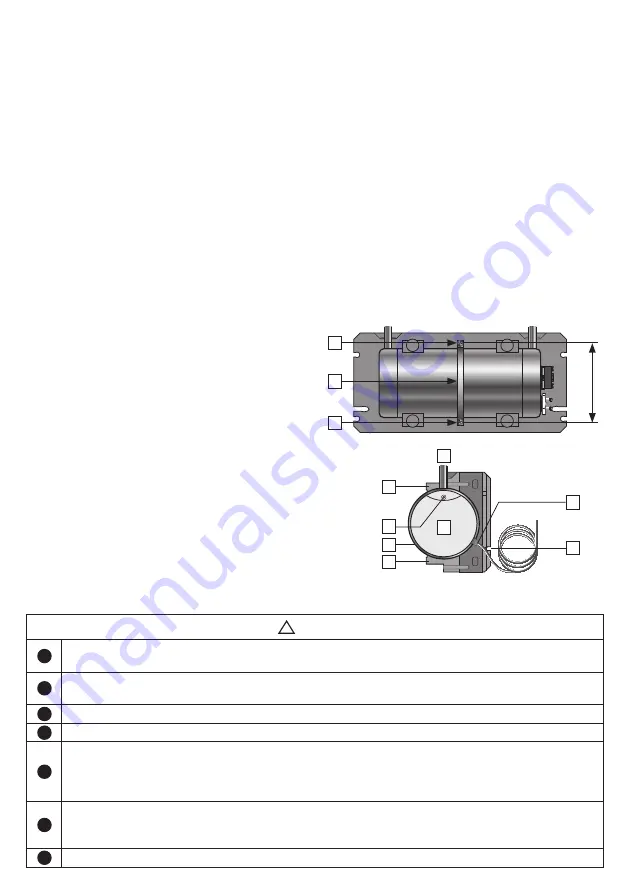
3.3.3 Wall fitting
The product is designed for to be mounted on a
wall When the insulation cap is removed, there is
easy access to the screw holes (D).
The Nano is attached to the wall with the mount-
ing band supplied (V); see illustration. The metal
band is bent/placed around the middle of the
tank and fixed to the wall through the holes in the
insulation, using the screws/washers supplied.
Ensure that the connectors do not press on the
insulation parts. Use bits of the torx type (T25).
Tighten the screws until the insulation around the
screw holes deforms.
3.3.4 Reversing the inner tank
For horizontal mounting, the inner tank can be
reversed if it is desirable to swap the CW and HW
connections for ease of fitting. Important: This
can only be done when the electricity is not con-
nected.
1. Remove the insulation (see 3.3.2).
2. Remove the electrical cover by loosening
the nut (E). Then unscrew the strain reliever
for the mains cable (F) and remove the elec-
trical cover.
3. The electrical cover (I) may be modified by
opening the alternative fixing for the strain
reliever (K). Material in the recess should be
E
H
H
K
F
J
G
I
removed and the strain reliever with cable
fitted into the new channel.
4. Remove the mounting band (V). Pull the
tank out so the connections clear the at-
tachment points (H). Turn the tank 180° and
push it back into the attachment points. Fit
the mounting band.
5. Ensure that connections and the coloured
rings (red/blue) indicating HW and CW are
positioned correctly in the slots.
6. Fit the electrical cover with the nut (E), then
fit the insulation cap. The end-parts of the
insulation must now swap places.
7. The product has built-in channels in the
back (J) for simple and tidy routing of the
mains cable at the back of the product.
D
V
D
C-C
174 mm


