background image

13

4.4 Smart Technology


Smart Control for water heaters will save en-

ergy and money for consumers by adapting 

the energy used to the typical household re-

quirements for water heating. When the water 

heater is first switched on, the smart control 

operates like a normal thermostat for 7 days, 

but during this time, will monitor and learn the 

habits of the household. After 7 days the smart 

control will reduce the energy used by the wa-

ter heater to match the requirements of the 

household. The smart system stays in learning 

mode and will alter the energy usage in a ac-

cordance with changes in household hot water 

usage. 80322/3 includes embedded software 

with a high performance algorithm which has 

been tested and approved in both laboratories 

and in field conditions.The algorithm has been 

also tested as per the procedure defined in 

prEN50440. 80322/3 

Thermostat software implements a self setting 

algorithm which is performed at first power 

ON and repeated throughout the product life 

whenever there is a need for product perfor-

mances optimization. This automatic setting 

determines a set of parameters in direct rela-

tionship with the power of the heating element 

and the tank capacity. 

The Smart Themostat is designed to be directly 

plugged into an immersion heating element 

and includes: 

• 

Mechanical double pole disk safety

• 

Safety limiter set between 65°C and 90°C 

depending on ESWH

• 

Manual reset safety

• 

LED indicator : Power, Error, Warm-up

• 

2 pins connector for remote LED (not used)

• 

Rotating knob for product setting

• 

Smart Sensor

• 

Horizontal or Vertical mounting

• 

Riveted tamper proof cover

• 

Screw pillar terminals

• 

Anti-Legionella function

• 

14A / 220V – 240V / 50 Hz / 3000 W max. 

4.5 Smart Control red LED indicator

The red LED on the top cover of 80322/3 Ther-

mostat Standalone provides information about 

product status as described in the table (right).

Thermostat 

probe sensor

Heating ele-

ment faston 

plugs

Safety disk

Rear view

Side view

2 pins connec-

tor for LED

Thermostat 

probe sensor

Heating ele-

ment faston 

plugs

LED 

mode

Description

Indication

Off

Off full time, or desired 

temperature is achieved

Product is in OFF mode 

or fully heated

Blinking every 

10 sec.

OFF for 10s and ON for 1s Product is ready and in 

normal operation

Solid ON

Full time ON

In normal operation - 

heating up in progress

Fast blinking

OFF for 1s and ON for 1s

Fault detected (see 

‘Causes of potential 

defects

Fast double 

blinking at start

2 times, OFF for 0.5s and 

ON for 0.5s

Confirmation of factory 

preset position of the 

rotating knob

Summary of Contents for Super Xpress SX iQ Series

Page 1: ...142228 02 08 2019 Super Xpress SX iQ 120 150 180 210 250 300 l EN SAFETY INFORMATION O M INFORMATION INSTALLATION MANUAL TDS TECHNICAL DATA SHEET ...

Page 2: ...ng of immersion heaters 10 4 3 Smart control settings 12 4 4 Smart technology 13 4 5 Smart control RED LED indicator 14 4 6 Software reset 14 4 7 Anti Legionella Cycle 14 4 8 Smart control OFF PEAK function 14 4 9 Smart control power supply 14 4 10 Smart control technical data 15 Symbols used in this manual WARNING Could cause serious injury or death CAUTION Could cause minor or moderate injury or...

Page 3: ... be filled with water before the power is switched on Maintenance settings should only be carried out by persons over 18 years of age with sufficient understanding CAUTION The product must not be exposed to frost over pressure over voltage or chlorine treat ment See warranty provisions Maintenance settings should not be carried out by persons of diminished physical or mental capacity unless they h...

Page 4: ...ylinder into position should be the last thing done before connection of pipes and commissioning of the cylinder This manual gives detailed advice for installation and should be read carefully prior to fitting any unvented unit OSO Super SX cylinders are not suitable for gravity fed primary systems In known hard water regions precautions should be tak en to prevent limescale formation in hot water...

Page 5: ...installed complying with current building regulations The product should be placed in a dry and permanently frost free position The product should be placed on a floor or wall suitable for the total weight of the prod uct when in operation See type plate The product must have a clearance for servicing of 400 mm in front of the immersion cover 150 mm above cylinder The product should be easily acce...

Page 6: ...racket 300 l only Tundish incl screws Plastic cable clamp Components factory fitted Expansion vessel s with T piece connector Flexible hose for expansion vessel Combination valve includes line strainer pressure reducing valve balanced cold water connection for shower or bidet only blank ing cap for balanced cold water connection temperature pressure relief valve and hot water blending valve Docume...

Page 7: ...g to BS EN 50525 2 11 Cables should be sufficient length to reach from the junction box through the base channels and leave an amount of tail from the front of the cylinder sufficient to reach the electrical connection point For more information about electrical installations see chapter 4 ELECTRICAL INSTALLATION 2 8 Pipework The OSO Super SX has all pipework connections at the top of the cylinder...

Page 8: ...n mixer showers Under no circumstances use the balanced cold connection to feed all cold water outlets as this practice contravenes Section 10 of water regulations If a balanced mains pressure cold water supply is required to a shower or bidet over rim type only ascending spray type requires type AA AB or AD air gap remove blanking cap and connect to the shower or bidet cold supply 2 on the combin...

Page 9: ...ghtness Open hot water tap furthest away from the OSO water heater 2 Open the mains stop cock to fill the water heater When water flows evenly from tap al low to run for a few minutes to flush through any dirt swarf or residue then close the tap Open successive hot taps to purge any re maining air 3 Check all water connections for leaks and rec tify if necessary 4 Manually operate Expansion relief...

Page 10: ...unted Upper immersion thermostat ThermODisc The recommended screw torque is 0 2 kp 2 0Nm End terminal fork width must not exceed 10 mm see illustration A safety cut out is also incorporated within the upper thermostat and will operate at 85 C 3 C Should this happen check reasons for thermal cut out button being released and when satisified press the reset button Important Before resetting the safe...

Page 11: ...ufacturers instruction for the ap propriate assembly of DIN 46228 4 Tubular end sleeves with plastic sleeve Use the appropriate crimping tool with correct jaw profile jaw length For Solid round single conductors an insulation strip length of 12mm 1 is suitable with no treat ment Upper diagram 1 shows wire cutting for solid wire lower diagram 2 for multiwire Cutting the cable wires to the lengths s...

Page 12: ... Max 60 C Manual mode Starting point 60 C Antifrost Min rotating position 6 C Power on LED Manual Reset Manual mode Max rotating position 70 C COTHERM iQuaFlex A T60 220 240V 14A B V D E S 4 3 5 2 6 1 A B 1 Electrical connectors Connector Description A Line connection B Neutral connection Earth Connects to grub screw on element head 4 3 Smart Control settings The rotating knob allows selection of ...
Page 13: ...e heating element and the tank capacity The Smart Themostat is designed to be directly plugged into an immersion heating element and includes Mechanical double pole disk safety Safety limiter set between 65 C and 90 C depending on ESWH Manual reset safety LED indicator Power Error Warm up 2 pins connector for remote LED not used Rotating knob for product setting Smart Sensor Horizontal or Vertical...

Page 14: ...will automatically perform full water heat cycle above 65 C 4 8 Smart Controll OFF PEAK function The 80322 3 thermostat can support smart function in off peak installation configuration The 80322 3 thermostat will automatically detect the installation in Off peak con figuration based on presence or absence of power supply during a day In smart mode the controller will self manage the adaptation of...

Page 15: ... each side of the product are recommended Manual reset cut out Manual reset of safety cut out can be applied after a minimum of 30 C drop in tank temperature Action Thermostat 1 B thermal cut out 2 B Extent of sensing elements Smart sensor regulation 1 disk safety cut off Rate impulse voltage 2500V Light connector Male XH 2 connector Light connector max current Forward voltage 3 2V for 20mA Maximu...

Page 16: ... recommended Important to check the precharge the expansion vessel must be completely empty of water if the pressure is different from the value shown on the label it must be restored to the original value Do not remove expansion vessel without depres surising the cylinder and draining 10 litres of water from the drain valve at the base of the cylinder 5 5 Guarantee Cylinder should be serviced ann...

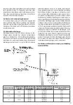
Page 17: ...o dis charge pipes should be suitably temperature rated as defined by G3 building Regulations The pipe must have a continuous fall and should terminate in a safe and visible place Downward discharges at low level i e up to 100 mm above external surfaces such as car parks hard stand ings grassed areas etc are acceptable providing that where children may play or otherwise come into contact with disc...

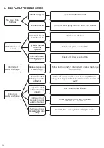
Page 18: ...lve not working properly Cold water inlet pressure reducing valve not working Temperature and pressure relief valve faulty Check and open stopcock Turn off water supply remove and clean strainer Check and switch on Check and press reset button Check and press reset button Follow instructions 5 2 Intermittent or slow discharge from tundish Switch off power to immersion heater s When dis charge has ...

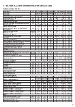
Page 19: ...peratingpressureofcylinder MPa Bar 3 3 3 3 3 3 Max operatingtemperatureofcylinder C 70 70 70 70 70 70 Expansionsolution GWS 3 5bar GWS 3 5bar GWS 3 5bar GWS 3 5bar GWS 3 5bar Aquasys tem 3 bar Expansionvesselcapacity L 6 2 x 6 2 x 6 2 x 6 2 x 6 24 Hydraulicconnections Secondaryreturn mm 15 15 15 15 15 15 Coldwater Inch 3 4 3 4 3 4 3 4 3 4 3 4 Hotwater Inch 3 4 3 4 3 4 3 4 3 4 3 4 Immersionheater I...

Page 20: ... Regulations 3 Failure to install and commission this appliance to the manufacturer s instructions may invalidate the guarantee The above does not affect your statutory rights For full details on the HWA charter please visit http www hotwater org uk HEATING AND HOTWATER INFORMATION COUNCIL IT IS THE RESPONSIBILITY OF THE INSTALLER TO COMPLETE THIS LOG BOOK AND PASS IT ON TO THE CUSTOMER FAILURE TO...

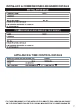
Page 21: ...IF DIFFERENT NAME DATE ADDRESS TEL No REGISTERED OPERATIVE ID CARD No IF APPLICABLE REGISTRATION DETAILS IT IS THE RESPONSIBILITY OF THE INSTALLER TO COMPLETE THIS LOGBOOK AND PASS IT ON TO THE CUSTOMER FAILURE TO DO SO MAY INVALIDATE THE CYLINDER GUARANTEE APPLIANCE TIME CONTROL DETAILS MANUFACTURER OSO HOTWATER UK MODEL CAPACITY TYPE TIME CONTROL UNVENTED PROGRAMMER litres SERIAL No TIME SWITCH ...

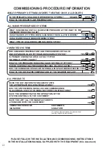
Page 22: ... IS THE PRESSURE REDUCING VALVE SETTING IF FITTED WHERE IS OPERATING PRESSURE REDUCING VALVE SITUATED NO YES NO YES NO bar HAS THE EXPANSION VESSEL OR INTERNAL AIR SPACE BEEN CHECKED YES NO WHAT IS THE HOT WATER TEMPERATURE AT THE NEAREST OUTLET C bar ALL PRODUCTS YES DOES THE HOT WATER SYSTEM COMPLY WITH THE APPROPRIATE BUILDING REGULATIONS HAS THE SYSTEM BEEN INSTALLED AND COMMISSIONED IN ACCORD...

Page 23: ...nual and all relevant Codes of Practice and Regulations in force at the time of installation The Product has not been modified in any way tampered with or subjected to misuse and no factory fitted parts have been removed for unauthorized repair or replacement The Product has only been connected to a domestic mains water supply in compliance with the European Drinking Water Directive EN 98 83 EC or...

Page 24: ...o COMMENTS SIGNATURE DATE ENGINEER NAME SERVICE 5 COMPANY NAME TEL No COMMENTS SIGNATURE DATE ENGINEER NAME SERVICE 7 COMPANY NAME TEL No COMMENTS SIGNATURE DATE ENGINEER NAME SERVICE 9 COMPANY NAME TEL No COMMENTS SIGNATURE DATE ENGINEER NAME SERVICE 2 COMPANY NAME TEL No COMMENTS SIGNATURE DATE ENGINEER NAME SERVICE 4 COMPANY NAME TEL No COMMENTS SIGNATURE DATE ENGINEER NAME SERVICE 6 COMPANY NA...

Page 25: ...25 Notes ...

Page 26: ...26 Notes ...

Page 27: ...27 Notes ...

Page 28: ... spareparts uk oso hotwater co uk E mail sales uk oso hotwater co uk Manufactured by OSO Hotwater AS Industriveien 1 3300 Hokksund Norway Tel 47 32 25 00 00 oso oso no www osohotwater com This installation manual and all its content is protected by copyright and may be reproduced or distributed only with written consent from the manufacturer We reserve the right to make changes without notice ...

Reviews: