background image

Installation 


________________________________________________________________________________  

page 3 

OSRAM operating instructions DALI Repeater LI


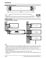
Design and dimensions 


Wiring schemes 

1. Repeater in DALI operation: 

L

N

PE

DA

DA

Hints: 

  Further DALI devices may be connected to the DALI control unit, e.g. DALI ECG or further 

repeaters. For maximum number of DALI devices please refer to the instructions of the control unit. 

  Maximum wire length at the output of the DALI Repeater is 300 m (in total over both outputs). 

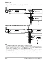
  Both outputs of the DALI Repeater LI are electrically interconnected. To simplify the connection the 

layout is done by pairs. 

  Outputs of different Repeaters may not be interconnected with each other. 

  In total over both outputs a maximum number of 64 DALI ECG or DALI REPEATERS may be 

connected. 

Summary of Contents for DALI Repeater LI

Page 1: ...III 2008 DALI Repeater LI 001240508GB ZPE 2433444 OSRAM GmbH www osram com ecg lms Customer Service Center CSC www osram de evg lms Steinerne Furt 6286167 Augsburg Germany Tel 49 1803 677 200 charges apply Fax 49 1803 677 202 ...

Page 2: ...unting e g for recessed ceiling installation is suitable Safety information The following information is provided for your safety Please read these operating instructions carefully before installing and using the DALI REPEATER LI This is the only way to ensure that you use the equipment safely and correctly Keep these operating instructions in a safe place for future reference You should make sure...

Page 3: ... DALI ECG or further repeaters For maximum number of DALI devices please refer to the instructions of the control unit Maximum wire length at the output of the DALI Repeater is 300 m in total over both outputs Both outputs of the DALI Repeater LI are electrically interconnected To simplify the connection the layout is done by pairs Outputs of different Repeaters may not be interconnected with each...

Page 4: ...rminals must not be connected The maximal overall wire length at the push button input should not exceed 100 m Further points of control can be achieved by parallel connection of several push buttons Push buttons with glow indication lamps in parallel to the push to make contact are inapplicable Both outputs of the DALI Repeater LI are electrically interconnected To simplify the connection the lay...

Page 5: ...tion LED and Service button Touch DIM operation Before first manual operation the DALI Repeater should be initialised as follows Initialise is started by pressing the integrated service button of the DALI REPEATER LI for at least 0 5 s During initialise process the highest minimal dimming level of the connected DALI devices is detected and stored During this process the LED will flash in yellow Af...

Page 6: ...n automatically As long as the functional test is active the indication LED of the repeater flashes alternating between green and yellow Service button The integrated service button of the DALI REPEATER LI provides following functionality During initialise process the highest minimal dimming level of the connected DALI devices is detected and stored It is started by pressing the integrated service...

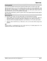
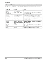
Page 7: ... activated by a short press on the service button flashing red green No DALI device at the output detected Broken wire connection at the output side or interruption of mains supply of the connected DALI devices yellow Lamp failure At least one of the connected DALI devices is indicating a lamp fail flashing yellow Initialising detection of highest minimal dimming level Initialise process was start...

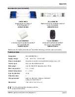
Page 8: ...p to 2 Touch DIM RC 4008321183033 Maintenance free battery less EnOcean transmitter technology inductive power generation Technical data Designation DALI REPEATER LI Supply voltage 100 240 V 50 60 Hz or DC Power consumption Depends on number of connected DALI devices max 4 W Control input DALI acc IEC 62386 102 201 DALI output max 64 DALI ECG respectivly max 130mA Wire cross section 0 5 1 5 mm 2 A...

Reviews: