background image

10

8. SYSTEM INSTALLATION INSTRUCTIONS

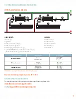
Mount the light fixture in a location according to your 

lighting design, per the installation steps for your purchased 

hardware. For Combo Mount, first mount the power supply to 

the structure in the same location as the fixture. Adjust the 

mounting height according to your lighting design, the bottom 

of the light fixture at least 18” above the plant canopy.

Mount the power supply in the desired location, per the installation 

steps for your purchased mounting hardware.

CAUTION:

 To protect the LED ARRAY,

•  Do NOT remove the protective cover during installation.

•  Do NOT contact the LED array or protective cover with sharp object or force that may damage the LED’s.

•  Do NOT leave the protective cover on the fixture after installation. It will melt when powering the fixture.

•  Do NOT plug in AC power BEFORE connecting the power supply to VYPR fixture first.

•  Also, the power supply heat sink fin edges may be sharp. The use of gloves is recommended when handling and installing the power 

supply to reduce the risk of injury. 

PRECAUCIÓN:

 Para proteger el LED ARRAY,

•  NO retire la cubierta protectora durante la instalación.

•  NO entre en contacto con la matriz LED o la cubierta protectora usando un objeto o fuerza afilado que pueda dañar el LED.

•  NO deje la cubierta protectora en el aparato después de la instalación. Se derretirá al encender elaparato.

•  NO conecte primero la alimentación de CA ANTES de conectar la fuente de alimentación a la unidad VYPR.

•  Además, los bordes de la aleta del disipador térmico de la fuente de alimentación pueden ser afilados.

•  Se recomienda el uso de guantes al tocar e instalar la fuente de alimentación para reducir el riesgo de lesiones. 

MISE EN GARDE

 : Pour protéger le réseau de DEL

•  NE PAS retirer le couvercle de protection pendant l’installation.

•  NE PAS mettre en contact la matrice de DEL ou le couvercle de protection avec un objet pointu ou une force qui pourrait endommager les DEL.

•  NE PAS laisser le capot de protection sur le luminaire après l’installation. Il fondra lors de la mise sous tension de l’appareil.

•  NE PAS brancher l’alimentation CA AVANT de connecter l’alimentation au luminaire VYPR.

•  De plus, les bords des ailettes du dissipateur thermique de l’alimentation électrique peuvent être coupants. L’utilisation de gants est 

recommandée lors de la manipulation et de l’installation de l’alimentation électrique afin de réduire le risque de blessure.

1

1

5

6

4

2

2

3

4

5

6

3a

3b

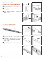
Connect the DC power extension cable to the 

power supply and light fixture, i.e. p/n CDCG-

71591-10 or CDCG-70720-10.

Remove the protective cover to expose the LED 

array. Discard the cover.

Connect the AC power cable to the power supply, 

i.e. p/n CACA-70754-10.  Wire to AC power per 

the system wiring diagram, or plug in AC power 

cables, and test.

Optional: if connecting to a dimmer system or 

controller, remove the dust cap on the power 

supply, and connect a Fluence wet location 

dimming cable, i.e p/n CDMA-71561-10.

Summary of Contents for Fluence VYPR 3p

Page 1: ...8 5 CULTIVATION BEST PRACTICE 8 6 GENERAL CARE 8 7 SYSTEM WIRING DIAGRAMS AND SPECIFICATIONS 9 8 SYSTEM INSTALLATION INSTRUCTIONS 10 9 MOUNTING INSTRUCTIONS 11 9 1 Combo Mount Hanger Kit Fixture and...

Page 2: ...RIX FOR LIGHT FIXTURE AND POWER SUPPLY EUROPE FAMILY MODEL PhysioSpec SPECTRUM INPUT VOLTAGE PACKAGING VR VYPR 3P Gen 3 PLUS BP6 BP8 HR9 DR9 DR5 BROAD R6 BROAD R8 DUAL R9B High Efficacy DUAL R9B DUAL...

Page 3: ...eflector Kit 20 inch 2 Kits N A N A N A ARV3 10529 40 40 Kits N A N A N A ARV3 10529 10 10 Kits A B C D E F G H I Light Fixture Power Supply Mounting Light Fixture Mounting Power Supply Mounting Refle...

Page 4: ...Power Supply to AC Line EUROPE Quantity per Power Supply Ordering Code QTY Carton A 1 83m 6 FT AC Extension Cable VDE Schuko Type F7 plug 230V AC 1 pc CACE 70774 10 10 pcs B 1 83m 6 FT AC Extension Ca...

Page 5: ...the light source reached its end of life the whole luminaire shall be replaced Horticulture Lighting not suitable for household room illumination 1 PPF calculations compiled using integrating sphere m...

Page 6: ...felel szell z s t AVVERTENZA IT Rischio di elettrocuzione Per ridurre il rischio di lesioni gravi si raccomanda di prendere sempre le dovute precauzioni e scollegare l apparecchio prima di spostarlo o...

Page 7: ...musi vykona v sulade s narodnymi pravnymi predpismi SLO Identifikacija izdelka v smislu OEEO Ne zavrzite med gospodinjske odpadke Izdelek in embala o je treba med odpadke zavre i ustrezno in v skladu...

Page 8: ...their own techniques Every crop is different and everyone has different goals However our internal research has given us insight into several strategies we would like to share Regularly check your pla...

Page 9: ...upply CACE 71576 10 and CCA pigtail cable CACE 71650 10 CABLING A AC Power Ground B AC Power Neutral C AC Power Line Main D 0 10V DC Dim E 0 10V DC Dim Power Supply Connector Connector Type Pin Assign...

Page 10: ...O conecte primero la alimentaci n de CA ANTES de conectar la fuente de alimentaci n a la unidad VYPR Adem s los bordes de la aleta del disipador t rmico de la fuente de alimentaci n pueden ser afilado...

Page 11: ...cation per the installation steps for your purchased mounting hardware Hook each hanger end onto the upper loops at each corner of the power supply Take 2 more mounting hangers as shown and Insert the...

Page 12: ...en the cooling fins 3 3a 1a 2 3b 1b 3 9 3 Parallel Mount Kit AMV3 10571 20 Suitable for 25 mm x 50 mm T slotted strut Front View 3 3 84 mm Take 2 mounting hangers Hang both brackets on the support str...

Page 13: ...mm in diameter and for trusses or channel up to 2 3 4 69 9 mm wide IMPORTANT DO NOT mount the power supply vertically using wire form type hangers To mount the power supply vertically use a Surface M...

Page 14: ...2 2 3 3 4 1 1 Power Supply Remote with Unistrut Pipe or Square Hanger Kit Take 2 mounting brackets and hang a bracket over the support structure Locate the holes for brackets on the narrow side of PS...

Page 15: ...rt the weight of the power supply PSU2 LVG HVE PSU2 HVG 1 52 38 62 mm PS Height 1 52 38 62 mm PS Height Place one bracket behind the power supply end plate and align the screw holes Install a screw an...

Page 16: ...cts for five years from date of purchase Contact us at support fluencebioengineering com for more warranty information We stand behind our research we stand behind our technology and we stand behind o...

Reviews: