background image


ExpressBox  7 x8G2- RAS 


7 PCIe (2.0 x8) Slot Expansion Systems with SNMP & DUAL PSU


EB7-x8-G2-RAS User Manual 


SKU: EB7-X8G2-RAS 


Summary of Contents for EB7-X8G2-RAS

Page 1: ...ExpressBox 7 x8G2 RAS 7 PCIe 2 0 x8 Slot Expansion Systems with SNMP DUAL PSU EB7 x8 G2 RAS User Manual SKU EB7 X8G2 RAS ...

Page 2: ...Communication Kit Optional 13 2 3 Attach Power and Expansion Cables 13 2 4 Recheck the Installation 14 2 5 Applying Power Correctly 15 2 5 1 Starting Up 15 2 5 2 Hardware Check 16 2 5 3 Software Driver Installation 17 2 5 4 Install Hot Plug Driver 18 2 5 5 Shutting Down 19 3 Verify Installation 20 3 1 Windows 20 3 2 Mac OS X 21 3 2 1 Expansion Slot Utility 21 3 3 Apple System Profiler 22 3 4 RedHa...

Page 3: ...12 1 High Performance Video Card expansion solutions 42 5 Chassis Maintenance 43 5 1 General Chassis Cleaning 43 5 2 Fan replacement 44 5 3 Hot Swappable Power Supply 45 5 4 Cleaning the Air Filter 46 6 Troubleshooting 47 6 1 Status Indicators and configuration switches 47 6 1 1 Status Panel indicators 47 6 1 2 Chassis Signal Detect Indicators 47 6 1 3 Chassis Slot Power Indicators 48 6 1 4 Chassi...

Page 4: ...chandise to OSS 61 8 Appendix A Need More PCIe Slots 62 8 1 Multiple PCIe Expansion System Configurations 62 8 2 The Fan Out Configuration 63 8 3 Daisy Chaining 64 8 4 PCI e Card Conflicts 65 8 5 Power On Sequence for Advanced Configurations 65 8 6 Troubleshooting Advanced Configurations 65 9 APPENDIX B I O Switching Via SNMP 68 10 APPENDIX C Compliance 73 ...

Page 5: ...efore handling the OSS Expansion chassis read the following instructions and safety guidelines to prevent damage to the product and to ensure your own personal safety Refer to the Advisories section for advisory conventions used in this manual including the distinction between Danger Warning Caution Important and Note Always use caution when handling operating the computer Only qualified experienc...

Page 6: ...rotecting Against Electrostatic Discharge Electrostatic Discharge ESD Warning Electrostatic Discharge ESD is the enemy of semiconductor devices You should always take precautions to eliminate any electrostatic charge from your body and clothing before touching any semiconductor device or card by using an electrostatic wrist strap and or rubber mat Static electricity can harm system boards Perform ...

Page 7: ...ring system and status panel a locator LED a redundant power supply and high volume cooling fans Features Easy Plug and Play installation Easily visible LEDs indicate correct installation PCI Express Hot Plug support on all 7 slots All slots support full length cards Transparent extension of PCI Express signals outside the computer 4U rugged black rack mount enclosure Constant critical component m...

Page 8: ... 4 x Linux Kernel 2 6x Solaris Warranty 1 Year Return to Factory Available Upgrade Options iPass Cable 3 meter MPN 60 00038 03 iPass Cable 7 meter MPN 60 00038 04 I2C over iPass communication kit MPN 01 05021 00 01 05022 00 Rack mount slide 18 26 28 MPN RSLIDES XX 1 2 PCIe Capabilities All slots support any combination of x1 x4 x8 and x16 PCI Express cards More specifically these notations refer t...

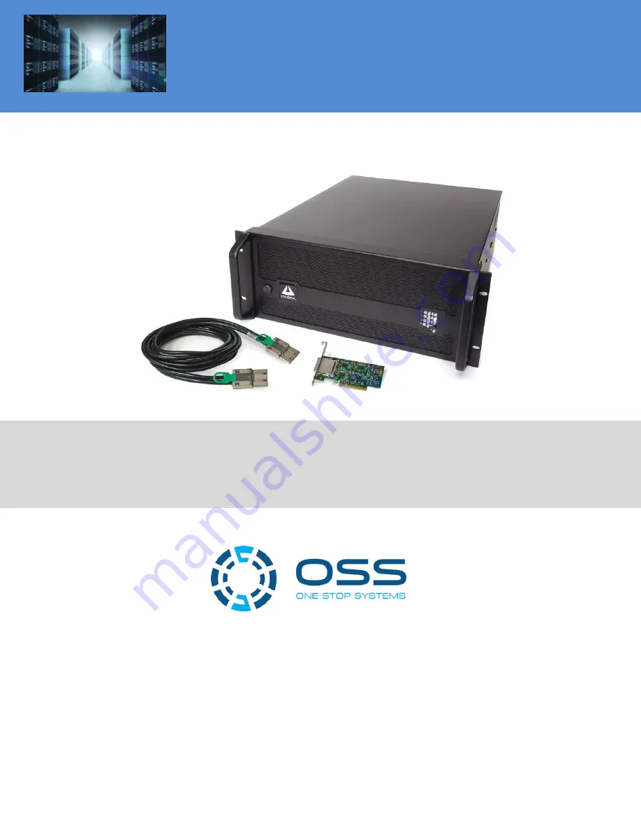
Page 9: ...ll of the required parts Gather all of the necessary tools required for installation Read this manual 1 4 Parts List The following parts are provided Item Qty Item 1 7 slot rack mount chassis 1 1 meter shielded iPass x8 cable 2 Half height PCI Express host card 2 U S Standard 115V power cord 1 Accessory Bag see contents in the next page 1 User s Manual 1 5 Tools Required for Installation ...

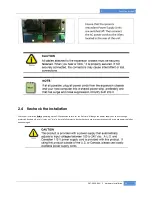
Page 10: ...t before removing the enclosure cover Turning the system power off at the power on off switch does not remove power to components High voltage is still present CAUTION Before touching anything inside the enclosure move to an ESD station and follow proper ESD procedures Failure to do so may result in electrostatic discharge damaging the computer or its components For more information see Protecting...

Page 11: ...l or system documentation The PCIe host card is a half height x8 capable PCIe card mounted to a full height bracket as shown below For low profile case applications you may need to change the mounting bracket to the low profile bracket that shipped with your system This is done by removing the screws that hold the card to the bracket Be sure you are using proper ESD procedures when completing this...

Page 12: ...ormation on using PCIe cards please refer to your computer s user manual or system documentation Next check the DIP switch settings on the OSS Host Card as shown Host Expansion Switch Default Host Note The expansion system will NOT function if SW1 is set to ON and the card is plugged into the host PC 2 2 2 Install Expansion interface card EIF As previously noted a Host Interface card HIF is the sa...

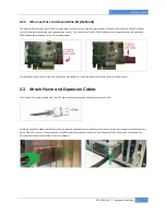
Page 13: ...he EIF as shown below For specific details on how to access the information provided by this interface please contact OSS technical support team 2 3 Attach Power and Expansion Cables The 1 meter iPass cable included with your OSS expansion chassis features a x8 connector on each side Carefully position the expansion chassis so that the supplied expansion cable will conveniently reach from the host...

Page 14: ...Check your installation before powering up the OSS expansion chassis for the first time Although the power supply has an over voltage protection device built into it it may not trip in time to fully protect a device that has been improperly connected or whose power cable has been damaged ...

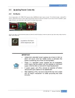
Page 15: ...the higher numbered PCIe buses in the PCIe bus hierarchy to be at a stable state when the host system issues its master power on bus reset Each of the redundant power supply units has its own power switch as well as an LED to indicate its power status After first turning on each of the individual power switches in the back of the chassis the entire system can then be turned on using the master pow...

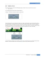
Page 16: ... the fact that the uplink is connected while LEDs 2 4 and 5 represent three PCIe cards that have been installed in slots 2 4 and 5 respectively The Linkup LEDs represent only an initial connection handshake between the chassis and host PC A successful linkup does not represent transfer or exchange of data For that the chassis features the activity LEDs The activity LEDs are visible from the inside...

Page 17: ...indows OS It may or may not be required for a Windows XP installation depending on your host system BIOS You should first install your 3rd Party card and connect the system as described earlier in this chapter The OSS software drivers should be installed only if you are having problems accessing the expansion or if you require the HotPlug feature Before attempting to install anything on a Windows ...

Page 18: ...on your computer 3 Click on the Winzip button to unpack the files into the C ExpressBox folder 4 Click on the OK button to confirm the files are unpacked 5 Click on the Close button to close WinZip 6 Go to the C ExpressBox folder and double click on the Setup exe file to start the driver installation 7 Follow instructions on the screen during the installation 8 Reboot your computer The setup progr...

Page 19: ... anticipated results please see Chapter 7 for information on how to contact OSS s Technical support team While every attempt was made to produce as universal a driver there may be compatibility issues with some systems At the same time the driver is flexible enough to be customized to a client s system by turning specific internal functions on and off 2 5 5 Shutting Down STOP DO NOT TURN OFF THE O...

Page 20: ... from the pop up menu Next click on Device Manager in the leftmost Computer Management window Finally click on the View Menu and select View Devices by Connection Open ACPI BIOS Open PCI Bus Click the sign several times until your reach a PCI Express Root Port with a PCI Standard PCI to PCI Bridge beneath it When installed properly you will see eight PCI Bridges ports below your system s PCIe Root...

Page 21: ...ystem should automatically recognize the OSS host card and expansion chassis 3 2 1 Expansion Slot Utility The following screen may be displayed the first time you turn on your computer with the OSS EB7 X8 RAS installed Choose OK MacOS X is prompting you to choose a PCI Express profile that maximizes the performance of your attached devices The OSS host card can communicate up to a bandwidth of x8 ...

Page 22: ...en using Mac OS X no additional software or drivers are needed As long as you are using Mac OS X Version 10 4 or newer the operating system should automatically recognize the OSS expansion chassis Select About This Mac under the Apple Icon Then click the More Info button click on the Devices tab you should see a pci bridge device listed under PCI as shown below Any PCIe Cards you install in the ex...

Page 23: ...ut the expansion system Typical output from lspci vvv is verbose but you can dig through the information to find very important information There are so many registers and settings associated with PCI Express Switches For example below is showing the OSS Chassis on Bus 7 Device 0 Function 0 Some information has been deleted but notice the Link Supported Speed is 5 0 Gb s Width x8 This is helpful t...

Page 24: ...e Integrated Device Technology Inc Unknown device 8037 prog if 00 Normal decode Link Supported Speed 5 0 Gb s Width x8 ASPM L0s L1 Port 2 Slot Number 1 PowerLimit 0 000000 08 04 0 PCI bridge Integrated Device Technology Inc Unknown device 8037 prog if 00 Normal decode Link Supported Speed 5 0 Gb s Width x8 ASPM L0s L1 Port 4 Slot Number 4 PowerLimit 0 000000 08 06 0 PCI bridge Integrated Device Te...

Page 25: ...ons for installing their card or hard drive on a desktop computer CAUTION Hardware installation shall be performed only by qualified service personnel per UL and IEC 60950 1 IMPORTANT We will provide reasonable technical support with 3P rd P Party PCIe cards However if you have verified a successful installation of the OSS expansion system as defined in HHHUUChapter 3 UUHHH but experience difficul...

Page 26: ...ws 1 Rotate the plastic pieces until their grooves are aligned with the cards 2 Unscrew the captive screw lift up and remove the apparatus 3 Tighten the screw in the black plastic piece to lock it into place and prepare it to lock the PCIe add in card that will be installed Reinsert the bar into the chassis and tighten the captive screw ...

Page 27: ...ON Before installing add in cards please ensure that the input current rating specified on the AC input label is not exceeded When installing 3rd Party PCIe cards into the OSS expansion chassis it makes no difference which PCIe slot you place your cards in Usually that is determined by accessibility and heat dissipation consideration as may be specified by the card manufacturer Be sure to install ...

Page 28: ...ystems should be at least PCIe Specification Revision 1 0 compliant or better Compliance in your system motherboard PCIe cards and console firmware or BIOS is your best assurance that everything will install and operate smoothly 4 3 System Should Be Up and Running Apply power to the OSS expansion chassis first then power up the computer Use the procedures detailed in UUChapter 3UUHHH to confirm th...

Page 29: ... laptop is sure to use a Hub with a regular network cable or a crossover cable without a Hub The SNMP module in the EB7 X8G2 RAS system is configured for DHCP access though this setting can be changed as described in the next section Once the chassis is turned on it will be assigned an IP address by your network s DHCP server If you have access to your network s DHCP server make sure to look up an...

Page 30: ...ow and press Enter The following browser window will open up The initial Generic Info page provides status information and no username or password is required If the main power switch is off then this page will show the IP Address that is currently assigned to the chassis the IP Address that will receive trap information the temperature settings and that the chassis is powered off To make changes ...

Page 31: ...em after a server had assigned it an IP address When you have finished configuring the network settings you can either configure the SNMP settings as described in the next section change the default user name and password or save the current changes by clicking on the Save Network Configuration button at the bottom of the screen Now you can connect your chassis to the network To find the IP addres...

Page 32: ...n IP Address to the IP address of the computer getting the SNMP data The default Trap Destination IP address in the above example was 192 168 1 2 Finally save the newly entered settings 4 4 5 Temperature settings In the Temperature section you can view in real time the temperatures inside the chassis Should the temperature rise above the set limit the respective value will be shown in red an audib...

Page 33: ...the screen 4 5 Reset to Default Values You can restore your EB7 X8G2 RAS chassis to the factory default values by pressing and holding the Alarm Reset Button for 10 seconds the Power LED will blink during this 10 second period When all values have been restored the LED will stop blinking and turn off 4 5 1 Configure your SNMP Agent If you use an SNMP agent to help you monitor your network you will...

Page 34: ...IB file has been loaded to an SNMP server via a front end software typically called a MIB Browser we can read in status information and set up specific functions otherwise not available via the Web interface The MIB Browser or equivalent front end SNMP software will display the OSS chassis MIB contents in an explorer like Tree interface A snapshot from the MIB Browser by iReasoning is shown below ...

Page 35: ...ions that essentially allow us to remote control the chassis Remote Chassis Reset turnPowerOffOn This function allows us to remotely turn the chassis off and on Right click on it and an options menu will appear Select the Set command IMPORTANT In order to successfully apply this function you must first set the SNMP Power on Jumper in the position between PS_ON and ON_BY_MCU This is not the default...

Page 36: ...sion chassis 4 7 Hot Swappable PCIe Card Installations New PCI Express technology allows you to remove your 3rd Party PCIe cards for maintenance or replacement without shutting down the system The EB7 X8G2 RAS expansions system supports Hot Plugging Hot Swapping of cards as defined by the PCI express specifications By design this feature allows the host PC to gracefully remove power to a slot so t...

Page 37: ...with you card s vendor that no such constrains exist for this card COMPATIBILITY ISSUE A documented compatibility issue exists between an Apple s MacBook Pro and G5 systems in conjunction with the EB7 X8G2 RAS chassis on which is connected an ATTO Technologies UL5D PCIe SCSI adapter In this configuration the Hot Plug feature needs to be disabled otherwise the system won t boot Each of the PCIe slo...

Page 38: ... button to close the new dialog 4 The properties dialog should close and the original Safely Remove Hardware dialog should remain Click on the Stop button of the dialog 5 A dialog with the title Stop a Hardware device should appear This is to confirm the stop command that will be sent to this device Click on the OK button of the new dialog 6 After a brief period a pop up will appear confirming tha...

Page 39: ... it should be added back to the list in the Safely Remove Hardware dialog 4 7 2 Hot Plug Swap Procedure for Linux 1 Set up a console as super user and run tail to receive messages sudo f var log messages 2 Open another console as super user and run modprobe pciehp sudo sbin modprobe pciehp 3 If there are any error messages in the first console run modprobe pciehp pciehp_force 1 sudo sbin modprobe ...

Page 40: ...nate Function DIP Switch The Alternate function DIP switch controls the following three functions Hot Plug Clock and power delivery behavior Actuator 1 Hot Plug Turns the Hot Plug function ON and OFF Its default position is Enabled in which case a Hot Plug controller supervises power delivery to the PCIe slots Actuator 2 Local Clock Turns on a local clock generated by the chassis itself independen...

Page 41: ...Gen II speeds J16 must be installed In case of the EB7x8 system J16 may remain open 4 10 EEPROM Write Protect WP J9 is used to enable or disable writing programming the EEPROM with new code Since EEPROM programming should be done only by OSS personnel it is recommended to keep write protection on 4 11 PCIe Switch I2C Address Setting SW9 is used to specify a different address for the PCIe switch in...

Page 42: ...k suite is optimized to work under Windows XP Vista Win7 and supports the latest DirectX and derivative 3D multimedia technologies In this environment a Gigabyte X58 UD5 was tested with various external PCIe video cards connected to Slot 1 PCIe x8G2 of the EB7 X8G2 RAS The motherboard has a Geforce 7600GS graphic card which is used an secondary monitor We first established a baseline by installing...

Page 43: ...uld perform a general cleanup of the chassis To perform a routine general cleaning of your chassis you will need the following 1 Can of compressed air proper distance 6 inches 2 Cotton Swabs 3 Isopropyl alcohol 4 Anti static wipes 5 Warm water for filter 6 Dish soap for filter Do not use a vacuum because vacuums create ESD First remove the four cover screws and the top chassis cover Next use a can...

Page 44: ...instructions and costs on shipping the chassis back for cleaning Finally clean the air filter following the instructions later in this chapter When finished replace the cover and turn on power to the system 5 2 Fan replacement The EB7 x8G2 RAS chassis was designed to allow hot swappable fan replacement while the chassis is powered on First you will need to remove the chassis lid as shown in the be...

Page 45: ...ed to the other module and sound an audible alarm If a power supply fails an alarm will sound to alert you of the problem Press the black button on the status panel on the front of the unit to stop the audible alert To replace a failed power supply simply grab the handle press down on the release lever at the top of the module and pull Replace the failed module with a new one and turn on the power...

Page 46: ...an this filter follow these simple steps First power down the chassis and then remove the screws on the side of the front panel with a Phillips screwdriver NOTE Note the different types of screws and where they go as you take them out Next open the faceplate slowly and disconnect the wire marked below Then remove the foam filter located behind the faceplate and clean it with a solution of warm wat...

Page 47: ...uld a problem occur with the chassis or a special mode of operation be solicited by the client we included below explanations as to what all these items are and how they should be treated 6 1 1 Status Panel indicators All LED s should be green at all times An orange LED means a fault of the corresponding item listed in the picture above 6 1 2 Chassis Signal Detect Indicators This group of LEDs D2 ...

Page 48: ... ON but there is no PCIe card in the slot the Power Off LED will be ON If the unit is NOT in Hot Plug mode the orange LED s should be all off If a slot has a card in it and the respective orange LED turns on that means there was a power fault in that slot If that is the case one needs to follow appropriate procedure to power down the host and then power down the chassis If the problem persists che...

Page 49: ...g conditions it should always be lit The activity LEDs will blink occasionally whenever the host is communicating with the card is a respective slot 6 2 SNMP Power On Source Jumper The SNMP module inside the EB7 X8G2 RAS chassis features a power on source jumper to select between local power on via the master on off switch and remote turn on via the SNMP software front end In order to gain access ...

Page 50: ...shooting steps My Computer Can t Find the PCIe Expansion System When Nothing Works My PCIe Card Doesn t Work My system hangs beyond a certain number of add in cards The OSS PCIe Expansion System is correctly displayed as a PCI standard PCI to PCI bridge in Windows Device Manager and as a pci bridge in the MAC Apple System Profiler and in Linux When connected and functioning correctly this Expansio...

Page 51: ...INK LEDs on the host and expansion cards should be ON if both PCIe slots are populated and both an uplink and a downlink iPass cable are connected properly The ACT activity LEDs will light blink only upon data transfers between host and expansion They can be off so long as the required LINK LEDs remain on Also verify the OSS PCI Express Host card is properly inserted into the host computer slot In...

Page 52: ... or chassis won t turn on or nothing seems to work correctly If it powers up OK but nothing works check the computer s Device Manager or System Profiler to see if the expansion system has been found If not found try the troubleshooting steps for My Computer Can t Find the PCIe Expansion System If the expansion system is visible but has a problem try to resolve the problem See Note above If that fa...

Page 53: ...e removed all 3P rd P Party PCIe cards from the OSS chassis and it still hangs try the following a Remove the OSS PCIe expansion host card from the computer and try booting up without the OSS expansion system attached i If it boots up OK without the OSS expansion system attached call OSS Technical Support ii If it still hangs the problem is in the computer and not with the OSS expansion system or ...

Page 54: ...ng a problem 3 Replace the problem card with a simple PCIe card such as an Ethernet card that has drivers built into the operating system Using this type of card will avoid any future questions about drivers possibly being installed incorrectly 4 Turn on the OSS expansion chassis and then turn on the computer Windows 5 Next open the Device Manager View by Connection selection If the is gone the pr...

Page 55: ...tallation of the OSS PCIe Expansion System as defined in Chapter 4 but experience difficulty installing your 3P rd P Party PCIe cards the card manufacturer should be able to provide the best support IMPORTANT The OSS PCIe Expansion System is designed to function exactly like your desktop computer This means that you should follow the card maker s instructions for installation on a Windows or Mac c...

Page 56: ... Technical Support for more help 6 3 4 My system hangs beyond a certain number of add in cards Any PCI or PCI Express expansion scheme requires the cooperation of the computer system s BIOS in order to operate properly regardless of the platform PC Laptop Server or operating system MS Windows MAC OS LINUX etc The BIOS hosts the first and the most fundamental code firmware that a computer executes ...

Page 57: ...de of the Slide pieces as shown Tighten finger tight only to allow for minor adjustment during assembly Depending on the depth of your rack you may select either the long or the short end bracket 6 4 1 Add Screws to Rack Post Attach 2 Panhead screws into the rack post where you want the chassis mounted Be sure you have measured accurately to ensure that everything fits in the rack correctly Leave ...

Page 58: ... as shown below Secure the slide rail to the rack with 2 screws to both front and rear posts After you have secured the slide rail fingers to the rack posts tighten the 2 screws used to attach the slide rail to the end bracket 6 4 3 Attach Chassis to Slide Rail The chassis mounts into the rack from the front Insert the chassis into the rack slide and press it forward until the chassis stops When t...

Page 59: ...nclude the diagnostic files they generate with your email 7 3 PCIScope Software Utility PCIScope is a powerful diagnostic tool for Windows designed by APSoft This software utility is a valuable resource to explore examine and debug the PCI subsystem of your computer It was made to fit the requirements of service personnel especially engineers programmers and system administrators and to integrate ...

Page 60: ...0 You should save this data as a file on your computer Please include your name and date as part of the file name with an extension of bpd This file should be included as an attachment when submitting a Technical Support request at Hwww OSS com TUsUTupportH ...

Page 61: ...d that you keep the packaging from the original shipment of your OSS product However if you return a product to OSS for warranty repair replacement or take advantage of the 30 day money back guarantee you will need to package the product in a manner similar to the manner in which it was received from our plant OSS cannot be responsible for any physical damage to the product or component pieces of ...

Page 62: ...to be lower 0 1 2 etc Once the BIOS is finished configuring everything and assigning resources the Operating System starts loading and activates the PCIe cards found When adding more Expansion Systems to an existing system be sure to connect and test them one at a time This will allow you to quickly resolve any connectivity or other issues right at the start DO NOT INSTALL any 3rd Party PCIe cards...

Page 63: ... into some 3rd Party PCIe cards is negligible nanoseconds and will not produce any visible effect on most systems It is only mentioned here because of certain specialized configurations involving unique PCIe cards with special software drivers The total number of logical buses that the data must pass through COULD make a difference See Chapter 5 Troubleshooting for more information if you suspect ...

Page 64: ...Local Bus by increasing the number of the logical PCI levels active in the system configuration The daisy chain configuration is therefore more popular among those who have only one available PCIe slot on the host computer but require additional slots downlink keeping in mind that more latency will be introduced every time we go from one expansion chassis to the other Verify your configuration Bef...

Page 65: ...ftware can read all available buses and properly configure all installed PCIe cards Obviously the reverse also remains true for shutting your system down The computer must be shut off BEFORE you attempt to turn off your Expansion System s 8 6 Troubleshooting Advanced Configurations When trying to troubleshoot problems with PCIe cards in a multiple expansion system configurations it is vital to cor...

Page 66: ... Need More PCIe Slots 66 Finding the Problem Card Windows If you need help to determine which PCIe card or which expansion chassis has the problem you can right click on the card with the and check the information contained in the Location field ...

Page 67: ...he Properties Window and then go to the Windows Error Code section for information on how to resolve this issue MAC and Linux If you have already reinstalled and reseated everything according to instructions in Chapter 2 and the PCI to PCI Bridge is still not visible in the Apple System Profiler call OSS Technical Support ...

Page 68: ...0 and 1 each connected via an iPass cable to the two servers Finally this test was performed under VMware ESX4 1 Step 1 Make sure all systems are off after doing so connect both servers to the uplink EIF card in the OSS chassis Do not turn the servers on just yet The dual uplink is labeled Server 1 and Server 2 which correspond to the specified fiber ports as shown below Make sure the chassis is o...

Page 69: ... and install the PCI device Step 5 In preparation for switching the I Os over to Server 2 uninstall the PCI device from the Device Manager of Server 1 Next open the web UI for the chassis set to 192 168 1 10 and your browser will show the SNMP web interface for the chassis Navigate to the tab labeled I O Failover and you will find the default I O configuration ...

Page 70: ...has all the I Os Step 6 Switch all I Os to server 2 the secondary server by clicking the button Switch All I O Ports in the web interface You will be directed to a temporary waiting page that looks like this After 10 seconds or so the page will automatically change back to the I O Failover tab where you should be able to note that the I Os have been switched to Server 2 ...

Page 71: ...condary server is ready to handle the transferred I Os you can now boot it up into VMware ESX 4 1 After FULLY BOOTING up server 2 connect to Server 1 via VSphere and set up a pass through on server 2 Since both server 1 and 2 are hardware identical our PCIe device remains at 08 00 0 and 08 00 1 Reboot server 2 and add the PCIe device to the guest OS ...

Page 72: ...pplications that generate I O traffic Step 8 Open up the SNMP web UI once again and switch the I O back over to Server 1 Be sure to leave the backup server on while doing this Once you switch I O back to server 1 your new I O Failover page will resemble the initial one in the beginning of the process Step 9 You are now ready to boot up the primary server server 1 Once you fully boot up your primar...

Page 73: ...5 of the FCC Rules Operation is subject to the following two conditions 1 this device may not cause harmful interference and 2 this device must accept any interference received including interference that may cause undesired operation Changes or modifications not expressly approved by the party responsible for compliance could void the service personnel s authority to operate the equipment NOTE Th...

Page 74: ...Ones Stop Systems EB7 X8G2 RAS 74 Manual P N 09 09919 02 rev A3 ...

Reviews: