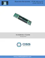
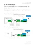
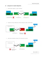
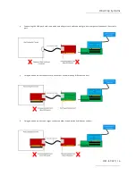
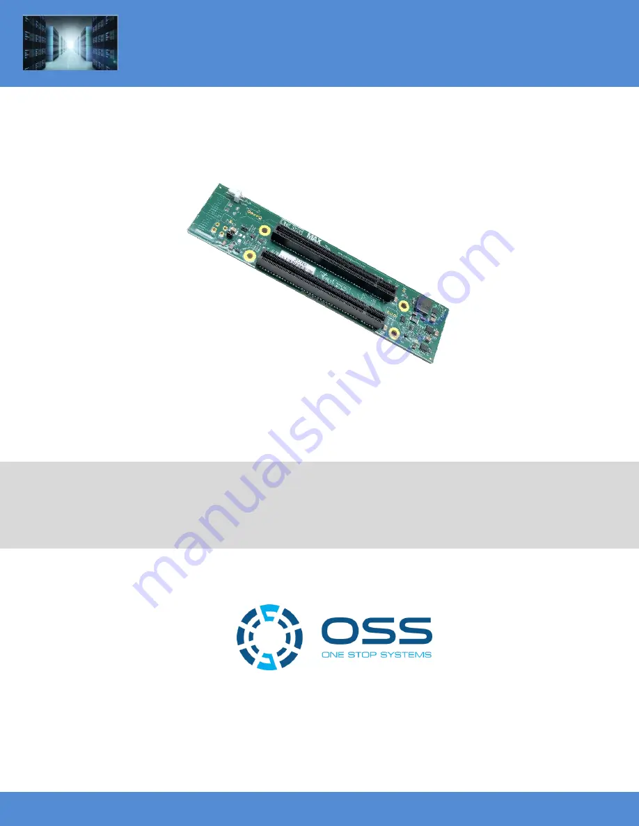
background image


Expansion Backplane, 1 PCIe slot x16 3.0   

Model: OSS-BP-427  

www.onestopsystems.com 


Installation Guide 


SKU: OSS-BP-427 


Summary of Contents for OSS-BP-427

Page 1: ...Expansion Backplane 1 PCIe slot x16 3 0 Model OSS BP 427 www onestopsystems com Installation Guide SKU OSS BP 427 ...

Page 2: ...x8 or x16 iPass Cable 18 2 3 4 Power Supply 19 2 4 Software Requirement 20 3 Installation Procedures 21 3 1 Connect Power Supply 21 3 1 1 Plug in External Power Brick 21 3 1 2 Standard ATX Power Supply 22 3 1 3 4pin to 12V Adapter Cable 22 3 2 Install OSS Target 23 3 3 Install Host card 23 3 5 Install PCIe card 24 3 6 Connect iPass Cable 24 3 7 Connect Power Cord 25 3 8 Power ON the system 26 4 Ve...

Page 3: ...27 3 5 3 The Red LED on the board stays LIT all the time 29 5 4 My PCIe cards is not getting detected 29 6 How to Get More Help 30 6 1 Contacting Technical Support 30 6 2 Returning Merchandise 30 6 3 Online Support Resources 30 ...

Page 4: ...o help you CAUTION Used to indicate and prevent the following procedure or step from causing damage to the equipment WARNING Used to indicate and prevent the following step from causing injury DANGER or STOP Used to indicate and prevent the following step from causing serious injury or significant data loss Disclaimer We have attempted to identify most situations that may pose a danger warning or ...

Page 5: ...ause your installation to produce emissions that could interfere with other electronic equipment in the area of your system When Working Inside a Computer 1 Before taking covers off a computer perform the following steps 2 Turn off the computer and any peripheral devices 3 Disconnect the computer and peripheral power cords from their AC outlets or inlets in order to prevent electric shock or syste...

Page 6: ...h can include wrist straps and smocks when servicing equipment You can also take the following steps to prevent damage from electrostatic discharge ESD When unpacking a static sensitive component from its shipping carton do not remove the component s anti static packaging material until you are ready to install the component in a computer Just before unwrapping the anti static packaging be sure yo...

Page 7: ...er 1 x16 PCIe Gen 3 Endpoint Slot One PCIe x16 3 0 expansion slot x16 mechanical x16 electrical LED Indicator 3 3VStandby Indication Operating Temperature 0 C to 85 C environment Operating Humidity 10 to 90 relative humidity non condensing Storage Humidity 5 to 95 relative humidity non condensing Industry Specifications PCI Express Card Electromechanical Specification Rev 3 0 PCI Express Base Spec...

Page 8: ...slot accommodates x2 x4 x8 and x16 PCie cards Target slot Also known as Upstream slot Designed for the Target card only It is a Gen3 x 16 slot electrical and mechanical PS_ON Enable force power ON Forces the power supply to be ON all the time 12VDC IN Connector ATX Input Power Use for connecting an external power supply Fan Connector For connecting external fan ...

Page 9: ...One Stop Systems OSS BP 427 9 1 2 1 Connector Pinouts 1 3 Block Diagram 1 4 Dimensions ...

Page 10: ... the x4 Connector B20 PETn1 A20 GND B21 GND A21 PERp1 B22 GND A22 PERn1 B23 PETp2 A23 GND B24 PETn2 A24 GND B25 GND A25 PERp2 B26 GND A26 PERn2 B27 PETp3 A27 GND B28 PETn3 A28 GND B29 GND A29 PERp3 B30 RSVD A30 PERn3 B31 PRSNT_X4 A31 GND B32 GND A32 RSVD B33 PETp4 A33 RSVD End of the x8 Connector B34 PETn4 A34 GND B35 GND A35 PERp4 B36 GND A36 PERn4 B37 PETp5 A37 GND B38 PETn5 A38 GND B39 GND A39 ...

Page 11: ...n13 A71 GND B72 GND A72 PERp13 B73 GND A73 PERn13 B74 PETp14 A74 GND B75 PETn14 A75 GND B76 GND A76 PERp14 B77 GND A77 PERn14 B78 PETp15 A78 GND B79 PETn15 A79 GND B80 GND A80 PERp15 B81 PRSNT_X16 A81 PERn15 B82 RSVD A82 GND 1 6 x16 End Point Slot Connector Pin Outs Pin Name Pin Name Mechanical Key B1 12V A1 GND B2 12V A2 12V B3 12V A3 12V B4 GND A4 GND B5 SMCLK A5 NC B6 SMDAT A6 REFCLK2 B7 GND A7...

Page 12: ... GND A32 RSVD B33 PERp4 A33 RSVD End of the x8 Connector B34 PERn4 A34 GND B35 GND A35 PETp4 B36 GND A36 PETn4 B37 PERp5 A37 GND B38 PERn5 A38 GND B39 GND A39 PETp5 B40 GND A40 PETn5 B41 PERp6 A41 GND B42 PERn6 A42 GND B43 GND A43 PETp6 B44 GND A44 PETn6 B45 PERp7 A45 GND B46 PERn7 A46 GND B47 GND A47 PETp7 B48 PRSNT_X8 A48 PETn7 B49 GND A49 GND B50 PERp8 A50 RSVD End of the x16 Connector B51 PERn...

Page 13: ...1 B66 PERp12 A66 GND B67 PERn12 A67 GND B68 GND A68 PETp12 B69 GND A69 PETn12 B70 PERp13 A70 GND B71 PERn13 A71 GND B72 GND A72 PETp13 B73 GND A73 PETn13 B74 PERp14 A74 GND B75 PERn14 A75 GND B76 GND A76 PETp14 B77 GND A77 PETn14 B78 PERp15 A78 GND B79 PERn15 A79 GND B80 GND A80 PETp15 B81 PRSNT_X16 A81 PETn15 B82 RSVD A82 GND NC NOT CONNECTED ...

Page 14: ...to use to ensure the product works properly 2 1 Supported Configuration The block diagram below shows the supported and valid configuration This illustrates the proper way to set up and how to use the OSS BP 427 board correctly 1 Using an OSS PCIe Host and Target adapter cards 2 Using a single compatible OSS Thunderbolt2 Option card ...

Page 15: ...Invalid Configuration 1 Connecting Other Backplane or similar to OSS BP 427 2 Using an unknown target adapter card or other brand of adapter card made by different vendor 3 Connecting to host computer via onboard built in iPass cable port connector ...

Page 16: ... board to an unknown adapter card and connecting to host computer via onboard iPass cable port 5 Using an unknown host adapter card or another brand made by different vendor 6 Using an unknown host and target cards or another brand made by different vendor ...

Page 17: ...l power supply options to use o External Power Brick Supply 180 watt AC Input 100 240V 2 5A 50 60Hz DC Output 12V 15 0A This require to a Power Cable Adapter part 80 520 5343 RC for connecting between the power supply and the board o Standard ATX power supply that has 4pin 12v connector 2 3 1 PCIe Slot Motherboard Requirement Use a computer motherboard with a Gen3 x16 or Gen3 x8 PCIe slots 2 3 2 H...

Page 18: ...et Photos below represent each card switch settings Target card mode switch settings Host card mode switch settings 2 3 3 x8 or x16 iPass Cable Use either x8 or x16 iPass cables for linking host card and target card together Preferably use a 1 or 1 5 meter long cable When using a x8 host and target cards you need to use x8 iPass cable x16 host and target card use x16 IPass cable Photos below are x...

Page 19: ...rd ATX power supply 1 External Power Brick Photo below is an example of an external power brick 180 watt AC Input 100 240V 2 5A 50 60Hz DC Output 12V 15 0A This requires a Power Cable Adapter part 80 520 5343 RC for connecting between the power supply and the OSS 427 board The INPUT power connector on the OSS 427 backplane has 4 pins see photo below ...

Page 20: ...volt cable is polarized so it can only be plugged into the 4 pin board connector correctly The motherboard connectors and the OSS backplane have the same square and rounded arrangement so the power cable only fits in one way 2 4 Software Requirement 1 Computer running Windows 7 8 10 and or Server 2 No driver is needed for the Host card Target card and backplane ...

Page 21: ...hows you how to connect an external power brick or a standard power supply to OSS 427 board You can either use an external power brick or a standard ATX power supply 3 1 1 Plug in External Power Brick Connect the cable power adapter and external power brick supply together sees photos below Plug in the ATX 12V cable connector to the INPUT connector on the OSS 427 backplane ...

Page 22: ...the OSS 427 board 3 1 3 4pin to 12V Adapter Cable If the power supply does not have a 4pin 12V connector you can use a 4 Pin MOLEX to ATX P4 CPU 4Pin 12V adapter cable see photo below You can buy this from any online electronic stores You are only connecting the power supply to the OSS 427 board DO NOT plug in the power cord yet CAUTION Do not attempt to plug in the power cord to the power supply ...

Page 23: ...x8 Target card Once you have identified the correct card to use plug the Target card into the Upstream slot on the OSS 427 board See photo below for the right location of the Upstream slot 3 3 Install Host card Power down the host computer first before installing the host card Do not install the host card while the computer is ON as this can cause electrical short and damage motherboard and the ca...

Page 24: ...rd in the expansion backplane Use the available downstream slots on OSS backplane See photos below 3 6 Connect iPass Cable In this example we are using a x8 iPass cable Connect the PCIe iPass x8 cable between the host and target cards Plug in the cable to the host card Plug in the other end of the cable to the target card Make sure the cable is firmly latched into the cable connectors of the card ...

Page 25: ...ing an external power brick simply plug in the power cord to the brick Upon connecting the power cord to the power supply the OSS 427 board will be on a stand by power mode and the RED LED on the board will illuminate as RED see photo below The RED LED will turn OFF as soon as the OSS 427 board is initialized by powering UP the host computer and when there is a link between Target card and Host ca...

Page 26: ...the computer s motherboard and it is fully seated 4 Ensure that the downstream slot on the OSS 427 backplane is populated with your PCIe card and is fully seated in the slot 5 Is the Power supply cable connected to the INPUT power connection on the OSS 427 board If everything is checked out GOOD next is to turn ON the main power of the host computer Upon powering ON the Host system it will send a ...

Page 27: ...CBL and EDGE LEDs 3 x8 CBL and EDGE LEDs 4 1 3 LED Definition PWR Board has power CBL Signal detect on cable EDGE Signal detect on card edge Signal detect does not mean it has a link but rather it identifies there is a signal on the card edge If the link does not appear to be stable it could mean that there is a compliance pattern being generated by the PCIe device interfacing with this card If th...

Page 28: ... is up at Gen1 1Hz Fast blink Link is up at Gen2 2Hz On solid Link is up at Gen 3 speed Multiple LEDs and Dip switches make debugging and troubleshooting easy Visible CBL and EGDE LEDs show PCIe link STATUS that each PCIe Interface card is operating properly Other LED for Power Good PWRGD is useful visual indicator for troubleshooting and verifying the connections A Gen3 LINK between host and targ...

Page 29: ...at your OSS 427 board is faulty or you may have a components failure on the board a Contact OSS Technical Support You may need to send the board for repair if it is under warranty b Buy a replacement board 2 If the board is not getting initialized the RED FAULT LED will stay ON a You may need to check your Host and Target cards i Reseat the Target and Host card ii Swap or replace the Target card a...

Page 30: ...and your return address on the shipping label when you return the item s for service Please note that One Stop Systems WILL NOT accept COD packages so be sure to return the product freight and duties paid Ship the well packaged product to the address below Attention RMA ________ One Stop Systems 2235 Enterprise Street 110 Escondido CA 92029 USA It is not required though highly recommended that you...

Page 31: ...One Stop Systems OSS BP 427 31 ...

Reviews: