background image

One Stop Systems 


OSS-KIT-EXP-2050| 12 


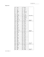
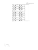
Pin-out for the PCIe x4 Card Edge Connector on the “Host Cable Adapter”   

 
Pin 

 
Side B 

 
Side A 

 
Name 

 
Description 

 
Name 

 
Description 

N/C 

N/C 

PRSNT1# 

Hot-Plug presence detect 

N/C 

N/C 

N/C 

N/C 

N/C 

N/C 

N/C 

N/C 

GND 

Ground 

GND 

Ground 

NC 

N/C 

N/C 

Not connected 

6  

N/C 

N/C 

JTAG3 

TDI (Test Data Input) 

GND 

Ground 

JTAG4 

TDO (Test Data Output) 

+3.3V 

3.3 V power  

N/C  

Not connected 

N/C 

Not connected 

N/C 

Not connected 

10 

3.3Vaux 

3.3 V auxiliary power 

+3.3V  

3.3 V power 

11  

 N/C 

N/C 

PERST# 

Fundamental reset 

Mechanical key 

12 

RSVD 

Reserved 

GND 

Ground 

13  

GND  

Ground  


Reference clock (differential 
pair) 

14 

PETp0 

Transmitter differential pair, 
Lane 0 

REFCLK 

15 

PETn0 

GND 

Ground 

16 

GND 

Ground 

PERp0 

Receiver differential pair, Lane 0 

17 

PRSNT2# 

Hot-Plug presence detect 

PERn0 

18 

GND 

Ground 

GND 

Ground 

19 

PETp1 

Transmitter differential pair, 
Lane 1 

RSVD 

Reserved 

20 

PETn1 

GND 

Ground 

21 

GND 

Ground 

PERp1 

Receiver differential pair, Lane 1 

22 

GND 

Ground 

PERn1 

23 

PETp2 

Transmitter differential pair, 
Lane 2 

GND 

Ground 

24 

PETn2 

GND 

Ground 

25 

GND 

Ground 

PERp2 

Receiver differential pair, Lane 2


26 

GND 

Ground 

PERn2 

27 

PETp3 

Transmitter differential pair, 
Lane 3 

GND 

Ground 

28 

PETn3 

GND 

Ground 

29 

GND 

Ground 

PERp3 

Receiver differential pair, Lane 3 

30 

RSVD 

Reserved 

PERn3 

31 

PRSNT2# 

Hot-Plug presence detect 

GND 

Ground 

32 

GND 

Ground 

RSVD 

Reserved 


Summary of Contents for OSS-KIT-EXP-2050

Page 1: ...PCIe x4 Gen2 Host to ECA Kit User Manual PCIe x4 Gen2 Host to ECA Kit 2050 SKU OSS KIT EXP 2050 www onestopsystems com ...

Page 2: ...ard 6 2 Component Identification 7 2 1 Host cable adapter card 7 2 2 Expansion Cable Adapter 8 3 Installation Instructions 9 3 1 Installing the Adapter Kit 9 3 2 Using the ECA 9 3 3 Operation 10 3 4 Using any Third party I O device 10 3 5 Removing the PCIe cable 10 4 Technical Information 11 4 1 Signal Adjustment 11 4 2 Pin Assignments 11 4 3 PCI Express x4 Connector PIN Assignment 14 5 Contacting...

Page 3: ... board with four screw mounting holes and can be mounted into an enclosure The ECA slot operates at x4 speeds but its x16 connector can accommodate a PCIe x4 x8 or x16 add in card The Cable Expansion Kit 2000 allows you to operate any PCI Express based device remotely over a cable Gen 2 products operate at 5Gb s per lane or twice the bandwidth of Gen 1 products Therefore PCIe x4 Gen 2 products ope...

Page 4: ...s x4 x8 16 slot on the host motherboard The Target adapter card operates ONLY in the OSS backplane target slot Both Host and Target adapter cards have PWR and CBL LED indicators Support half height bracket The Host and Target cable adapter cards require no software drivers 1 2 3 x4 Link Cable Available in 1m 2m 3m 5m 7m lengths PCI SIG Express Cable Specification Compliant Includes x4 PCIe lane an...

Page 5: ...11 ms pulse Vibration 5 17 Hz 0 5 double amplitude displacement 7 2000Hz 1 5g acceleration Power Consumption 3 75W typical 3 3 1 3A Agency Compliance FCC Class B CE ROHS Temperature Range 0 to 50 C 32 to 122 F 1 3 2 PCIe x4 Cable PCIe x4 Cable SKU OSS PCIe CBL x4 1M 1 meter long cable Cable Length 1m 2m 3m 5m 7m Circuits loaded 38 Gender Male to Male Lock to Mating Part Yes Material Metal Zinc All...

Page 6: ... Molex 75586 0010 Front Panel Indicators Power On Cable Present LEDs Power Consumption 3 75W maximum 3 3V 1 75 2 6W 5A 5 Vaux Temperature Range 0 to 50 C 32 to 122 F Relative Humidity 10 to 90 non condensing Shock 30g Acceleration peak 11 ms pulse Vibration 5 17 Hz 0 5 double amplitude displacement 7 2000Hz 1 5g acceleration Red drivers Pericom PI2EQX4401 Agency Compliance UL60950 FCC Class B CE s...

Page 7: ...the target cable adapter The host adapter inserts into the host computer s PCIe x4 x8 or x16 slot The host cable adapter Part OSS PCIe HIB25 x4 H allows communication between a processor and an I O point The target adapter inserts into the designated target slot Cable LED indicators are the same for both Host and Target configurations 2 1 2 Clock direction in Host configuration ...

Page 8: ...One Stop Systems OSS KIT EXP 2050 8 2 2 Expansion Cable Adapter 2 2 2 Clock direction in Host configuration ...

Page 9: ...4 slot It will still operate at x4 speeds Secure the cable adapter card 3 2 Using the ECA 1 Insert the x4 cable into the ECA card 2 Plug in the ATX power supply cable into the 24pin ATX power connector Note Sometimes an external load is necessary for ATX power supplies to regulate properly i e connecting hard drive power 3 Plug in the add in card or PCIe card in the available IO slot Endpoint slot...

Page 10: ...up the host system 3 The I O board will start automatically 3 4 Using any Third party I O device 1 The add in card or third party I O device must be installed in the endpoint slot expansion slot downstream port 2 Connect the external power source separate from the host system power supply to the add in card or PCIe card device if necessary 3 5 Removing the PCIe cable 1 To remove the cable press do...

Page 11: ...ilable for this purpose It is highly recommended to contact OSS customer support before making changes to these settings Having the customer solder to the board should void the warranty 4 1 Signal Adjustment 4 2 Pin Assignments Host and Target card connectors x4 Card Edge Connector The pins are numbered as shown with side A on the top of the centerline on the solder side of the board and side B on...

Page 12: ... Ground REFCLK Reference clock differential pair 14 PETp0 Transmitter differential pair Lane 0 REFCLK 15 PETn0 GND Ground 16 GND Ground PERp0 Receiver differential pair Lane 0 17 PRSNT2 Hot Plug presence detect PERn0 18 GND Ground GND Ground 19 PETp1 Transmitter differential pair Lane 1 RSVD Reserved 20 PETn1 GND Ground 21 GND Ground PERp1 Receiver differential pair Lane 1 22 GND Ground PERn1 23 P...

Page 13: ... detect PERn0 18 GND Ground GND Ground 19 PETp1 Transmitter differential pair Lane 1 RSVD Reserved 20 PETn1 GND Ground 21 GND Ground PERp1 Receiver differential pair Lane 1 22 GND Ground PERn1 23 PETp2 Transmitter differential pair Lane 2 GND Ground 24 PETn2 GND Ground 25 GND Ground PERp2 Receiver differential pair Lane 2 26 GND Ground PERn2 27 PETp3 Transmitter differential pair Lane 3 GND Ground...

Page 14: ...l Pair PERp3 B11 A12 PETn3 PERn3 B12 A14 CREFCLK Differential Pair CREFCLK A14 A15 CREFCLK CREFCLK A15 A17 SB_RTN Hook up Wire SB_RTN A17 A18 CPRSNT Hook up Wire CPRSNT A18 A19 CPWRON Hook up Wire CPWRON A19 B2 PERp0 Differential Pair PETp0 A2 B3 PERn0 PETn0 A3 B5 PERp1 Differential Pair PETp1 A5 B6 PERn1 PETn1 A6 B8 PERp2 Differential Pair PETp2 A8 B9 PERn2 PETn2 A9 B11 PERp3 Differential Pair PE...

Page 15: ... B30 A30 PERn3 PRSNT_X4 B31 A31 GND GND B32 A32 RSVD PETp4 B33 A33 RSVD End of the x8 Connector PETn4 B34 A34 GND GND B35 A35 PERp4 GND B36 A36 PERn4 PETp5 B37 A37 GND PETn5 B38 A38 GND PETp x PCI Express Transmit Positive signal of x pair PETn x PCI Express Transmit Negative signal of x pair PERp x PCI Express Receive Positive signal of x pair PERn x PCI Express Receive Negative signal of x pair ...

Page 16: ...B54 A54 GND PETn9 B55 A55 GND GND B56 A56 PERp9 GND B57 A57 PERn9 PETp10 B58 A58 GND PETn10 B59 A59 GND GND B60 A60 PERp10 GND B61 A61 PERn10 PETp11 B62 A62 GND PETn11 B63 A63 GND GND B64 A64 PERp11 GND B65 A65 PERn11 PETp12 B66 A66 GND PETn12 B67 A67 GND GND B68 A68 PERp12 GND B69 A69 PERn12 PETp13 B70 A70 GND PETn13 B71 A71 GND GND B72 A72 PERp13 GND B73 A73 PERn13 PETp14 B74 A74 GND PETn14 B75 ...

Page 17: ...2 GND A22 PETn1 B23 PERp2 A23 GND B24 PERn2 A24 GND B25 GND A25 PETp2 B26 GND A26 PETn2 B27 PERp3 A27 GND B28 PERn3 A28 GND B29 GND A29 PETp3 B30 RSVD A30 PETn3 B31 PRSNT_X4 A31 GND B32 GND A32 RSVD B33 PERp4 A33 RSVD End of the x8 Connector B34 PERn4 A34 GND B35 GND A35 PETp4 B36 GND A36 PETn4 B37 PERp5 A37 GND B38 PERn5 A38 GND B39 GND A39 PETp5 B40 GND A40 PETn5 B41 PERp6 A41 GND B42 PERn6 A42 ...

Page 18: ...D A64 PETp11 B65 GND A65 PETn11 B66 PERp12 A66 GND B67 PERn12 A67 GND B68 GND A68 PETp12 B69 GND A69 PETn12 B70 PERp13 A70 GND B71 PERn13 A71 GND B72 GND A72 PETp13 B73 GND A73 PETn13 B74 PERp14 A74 GND B75 PERn14 A75 GND B76 GND A76 PETp14 B77 GND A77 PETn14 B78 PERp15 A78 GND B79 PERn15 A79 GND B80 GND A80 PETp15 B81 PRSNT_X16 A81 PETn15 B82 RSVD A82 GND ...

Page 19: ...t contact OSS Service Representative to obtain a Return Merchandise Authorization RMA number Put this number and your return address on the shipping label when you return the item s for service One Stop Systems will return any product that is not accompanied by an RMA number Please note that One Stop Systems WILL NOT accept COD packages so be sure to return the product freight and duties paid Ship...

Page 20: ...One Stop Systems OSS KIT EXP 2050 20 ...

Reviews: