background image

One Stop Systems 


OSS-KIT-EXP-6002| 11 


4.


Board side pin-outs on both sides of the Link are identical. The cable assembly incorporates a null modem for the PCIe transmit and 
receive pairs. 
 

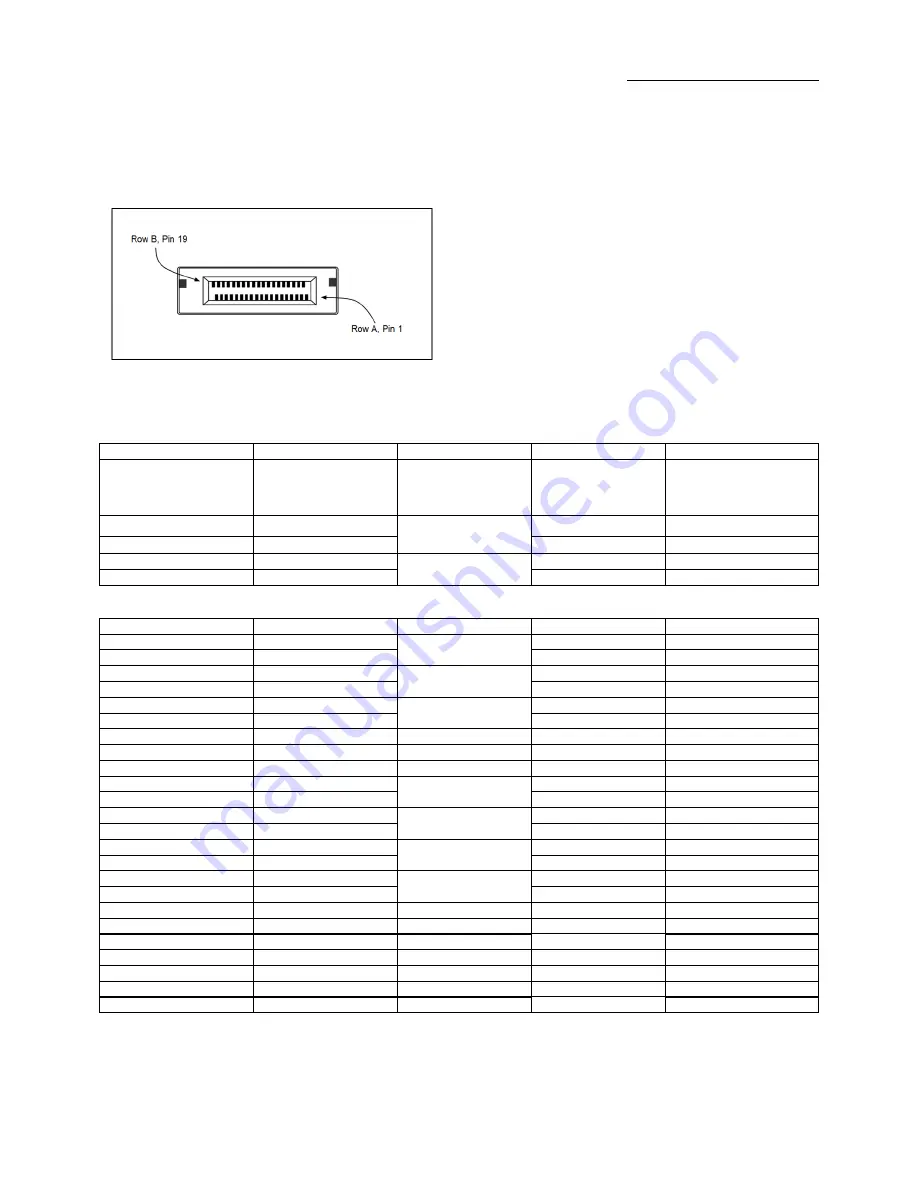
4.4  PCI Express x4 Connector PIN Assignment 


4.5  Pin-out for the PCIe x4 Cable 

Pin #  

Cable Side 1  


Cable Side 2  

Pin #  

A1 A4 A7 A10 A13 A16 B1 
B4 B7 B10 B13  

GND  

Drain Wires  

GND  

A1 A4 A7 A10 A13 A16 B1 
B4 B7 B10 B13  

A2  

PETp0  

Differential Pair  

PERp0  

B2  

A3  

PETn0  


PERn0  

B3  

A5  

PETp1  

Differential Pair  

PERp1  

B5  

A6  

PETn1  

PERn1  

B6  


Pin #  

Cable Side 1  


Cable Side 2  

Pin #  

A8  

PETp2  

Differential Pair  

PERp2  

B8  

A9  

PETn2  


PERn2  

B9  

A11  

PETp3  

Differential Pair  

PERp3  

B11  

A12  

PETn3  


PERn3  

B12  

A14  


Differential Pair  


A14  

A15  

CREFCLK  


CREFCLK- 

A15  

A17  

SB_RTN  

Hook-up Wire  

SB_RTN  

A17  

A18  

CPRSNT#  

Hook-up Wire  

CPRSNT#  

A18  

A19  

CPWRON  

Hook-up Wire  

CPWRON  

A19  

B2  

PERp0  

Differential Pair  

PETp0  

A2  

B3  

PERn0  


PETn0  

A3  

B5  

PERp1  

Differential Pair  

PETp1  

A5  

B6  

PERn1  


PETn1  

A6  

B8  

PERp2  

Differential Pair  

PETp2  

A8  

B9  

PERn2  


PETn2  

A9  

B11  

PERp3  

Differential Pair  

PETp3  

A11  

B12  

PERn3  


PETn3  

A12  

B14  

PWR  

NC  

PWR  

B14  

B15  

PWR  

NC  

PWR  

B15  

B16 

PWR_RTN  

NC  

PWR_RTN  

B16  

B17 

PWR_RTN  

NC  

PWR_RTN  

B17  

B18  

CWAKE#  

Hook-up Wire  

CWAKE#  

B18  

B19  

CPERST#  

Hook-up Wire  

CPERST#  

B19  

Back shell  

Chassis Ground  

Overall Cable Braid  

Chassis Ground  

Back shell  


Summary of Contents for OSS-KIT-EXP-6002

Page 1: ...Host Server to Expansion System Kit User Manual OSS KIT EXP 6002 SKU OSS KIT EXP 6002 www onestopsystems com ...

Page 2: ...s 8 3 1 Installing the Adapter Kit 8 3 2 Expansion link board 8 3 3 Removing PCIe Cable 8 3 4 Operation 8 4 Technical Information 9 4 1 Signal Adjustment 9 4 2 Pin Assignments 9 4 3 Pin out for the PCIe x4 Card Edge Connector on the Host Cable Adapter 10 4 4 PCI Express x4 Connector PIN Assignment 11 4 5 Pin out for the PCIe x4 Cable 11 4 6 Signal Descriptions 12 4 7 Connector Pin outs for the PCI...

Page 3: ...nto a PCIe slot of the server It then cables to a downstream expansion link board ELB The ELB acts as a downstream cable link board and the primary fan out switch to support multiple configurations of PCI express expansion slots The host adapter installs into a PCIe x4 x8 or x16 slot on the host motherboard It then cables to the expansion link board and installs in the SHB or system slot of a CPCI...

Page 4: ...1 3 backplane Support half height bracket The Host and Target cable adapter cards require no software drivers 1 1 2 x4 Link Cable Available in 1m 2m 3m 5m 7m lengths PCI SIG Express Cable Specification Compliant Includes x4 PCIe lane and side band signals for o Power ON o Reset o PCIe clock o Cable Present o Wake Positive latching mechanism per PCI SIG specification Support 10 Gbps full duplex tra...

Page 5: ...Dimension H x L 3 937 x 6 299 in 100 x 160 mm 1 slot wide Switch PLX PEX8733 32 lane switch Upstream Interface x4 PCI Express over cable PCI SIG PCI Express Cable Rev 2 0 Compliant Downstream Interface 16 lanes of PCI Express on the backplane connectors The lanes form two or four links to the backplane through the XP2 and XP3 connectors per the PICMG EXP 0 specification The following link modes ar...

Page 6: ...h 1m 2m 3m 5m 7m Circuits loaded 38 Gender Male to Male Lock to Mating Part Yes Material Metal Zinc Alloy Pitch Mating Interface 0 80mm 0 31 Single Ended No Water proof Dust proof Yes Wire Insulator Diameter N A Wire Size AWG 28 Wire Cable Type Round Electrical Current 1A Max per contact Shielded Yes Voltage Maximum 30V DC ...

Page 7: ...st computer s PCIe x4 x8 or x16 slot Cable LED indicators are the same for both Host and Target configurations 2 2 Expansion Link Board The Expansion Link Board ELB OSS CPCIe3 3U 6U ELB x4 is a downstream link board that installs into a CPCIe chassis The ELB fits into the system slot of a CPCIe backplane The ELB is the downstream link board and the primary fan out switch to support multiple config...

Page 8: ...on link board 1 Insert the expansion link board into the SHB slot on the chosen backplane 2 Connect the x4 PCIe cable to both cables adapter cards Press or pull the green TAB while slowly inserting the cable then release it to lock the cable See photos below 3 Test by pulling back on the connector 3 3 Removing PCIe Cable 1 To remove the cable press or pull the green tab and slowly pull the cable o...

Page 9: ...ilable for this purpose It is highly recommended to contact OSS customer support before making changes to these settings Having the customer solder to the board should void the warranty 4 1 Signal Adjustment 4 2 Pin Assignments Host and Target card connectors x4 Card Edge Connector The pins are numbered as shown with side A on the top of the centerline on the solder side of the board and side B on...

Page 10: ...er differential pair Lane 0 17 PRSNT2 Hot Plug presence detect PERn0 18 GND Ground GND Ground 19 PETp1 Transmitter differential pair Lane 1 RSVD Reserved 20 PETn1 GND Ground 21 GND Ground PERp1 Receiver differential pair Lane 1 22 GND Ground PERn1 23 PETp2 Transmitter differential pair Lane 2 GND Ground 24 PETn2 GND Ground 25 GND Ground PERp2 Receiver differential pair Lane 2 26 GND Ground PERn2 2...

Page 11: ... A8 PETp2 Differential Pair PERp2 B8 A9 PETn2 PERn2 B9 A11 PETp3 Differential Pair PERp3 B11 A12 PETn3 PERn3 B12 A14 CREFCLK Differential Pair CREFCLK A14 A15 CREFCLK CREFCLK A15 A17 SB_RTN Hook up Wire SB_RTN A17 A18 CPRSNT Hook up Wire CPRSNT A18 A19 CPWRON Hook up Wire CPWRON A19 B2 PERp0 Differential Pair PETp0 A2 B3 PERn0 PETn0 A3 B5 PERp1 Differential Pair PETp1 A5 B6 PERn1 PETn1 A6 B8 PERp2...

Page 12: ...B3 PERn0 B4 GND Ground reference B5 PERp1 Differential PCI Express Receiver Lane 1 B6 PERn1 B7 GND Ground reference B8 PERp2 Differential PCI Express Receiver Lane 2 B9 PERn2 B10 GND Ground reference B11 PERp3 Differential PCI Express Receiver Lane 3 B12 PERn3 B13 GND Ground reference B14 PWR 3 3V Cable Power B15 PWR B16 PWR_RTN Cable Power Return PETp x PCI Express Transmit Positive signal of x p...

Page 13: ...N B18 CWAKE Power management signal for wakeup events optional B18 CPERST Cable Reset 4 8 PCI Express x4 Connector PIN Assignment CFG 0 2 BP PORT CFG 0 1 2 A0 A1 A2 A3 B0 0 0 0 X4 X4 X4 X4 X4 0 1 0 X8 0 X4 X4 X4 0 1 1 X8 0 X8 0 X4 1 X X X16 0 0 0 X4 ...

Page 14: ...t contact OSS Service Representative to obtain a Return Merchandise Authorization RMA number Put this number and your return address on the shipping label when you return the item s for service One Stop Systems will return any product that is not accompanied by an RMA number Please note that One Stop Systems WILL NOT accept COD packages so be sure to return the product freight and duties paid Ship...

Page 15: ...One Stop Systems OSS KIT EXP 6002 15 ...

Reviews: