One Stop Systems
OSS-PCIe4-4UV-5
32
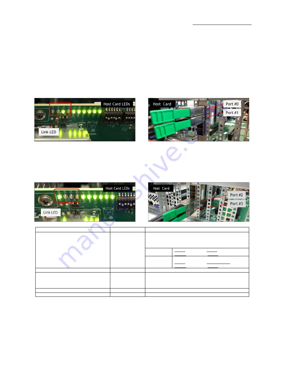
Host Card LED
(When Expansion and Host systems are ON)
Photos below are the link LED on the host card, set to x8 and with two cables connected.
CH0 illuminates when connected to host port 2 and 3, CH2 illuminates when connected to ports 0 and 1. For target, always illuminates CH0
1st cable connected to PORT #0
2nd cable connected to PORT #1
Photo below is the link led on the Host card set to x8 with two cables attached on the first bottom ports.
1
st
cable connected to PORT #2
2
nd
cable connected to PORT #3
LED
Status
Description
CH0 or CH2
ON (Solid Green)
There is a link between Host and Target cards.
Either CHO or CH2 LED will be ON, depending where the two cables are
connected on the ports of the HOST CARD.
CH2 (D3) Link
LED
1
st
cable is connected to PORT#0
2
nd
cable is connected to PORT#1
CH0 (D1) Link
LED
1
st
cable is connected to BOTTOM PORT#3
2
nd
cable is connected to PORT#2
LED0 (D2), LED1(D4), LED2(D6); LED3(D8)
ON (Solid Green)
Power Good
CE(D11)
ON (Solid Green)
Solid Green: Gen 4 on the expansion chassis switch
Blinking Green: The CARD EDGE connector is communicating to Gen3 PCIe
switch on the expansion board / backplane.
D10
ON (Blinking Green)
Power Good / FPGA Healthy
D9
ON (Solid Green)
AUX Power Good
Summary of Contents for OSS-PCIE-4UV-5-1
Page 5: ...One Stop Systems OSS PCIe4 4UV 5 5 ...
Page 16: ...One Stop Systems OSS PCIe4 4UV 5 16 ...
Page 70: ...One Stop Systems OSS PCIe4 4UV 5 70 6 2 pin aux power cable and pin outs ...
Page 83: ...One Stop Systems OSS PCIe4 4UV 5 83 14 Enclosure Dimensions ...
Page 84: ...One Stop Systems OSS PCIe4 4UV 5 84 15 Rackslide Mounting Position ...


