background image


19 

III.


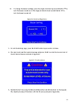
To change the buzzer settings, press the 

single-increment up second button


to 

turn the buzzer sound on, or the 

single-increment down second button 

 to 

turn the buzzer sound off. 


Figure 8.6.

 Buzzer settings menu. 


3.


To exit the Settings page, press the 

START

 button to proceed to continue. 


4.


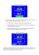
The user must read the caution message and press 

START

 to enter the main screen of 

the UV Ozone Cleaner as shown in 

Figure 8.7


Figure 8.7.

 Caution screen 


5.


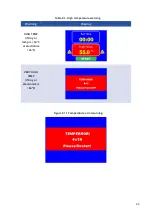
Modify the 

Set Time

 using the 

Minute (MIN)

 and 

Second (SEC)

 buttons on the keypad. 

The maximum value of the timer is 59 min 59 secs (as shown in 

Figure 8.8

). 


Summary of Contents for L2002A3

Page 1: ...Manual Version 3 0 A Product code L2002A3 Product Version 3 0 Software Version 3 0 ...

Page 2: ...ty Installation 9 3 8 Health and Safety Operation 10 3 9 Health and Safety Servicing 10 4 Unpacking 11 4 1 Packing List 11 4 2 Damage Inspection 11 5 Specifications 11 6 System Components 12 7 Installation 13 8 Operation 14 8 1 Overview 14 8 2 User Interface 16 8 3 Practical Operation 17 8 4 Program Operation 17 8 5 Operational Safety 21 9 Maintenance 23 9 1 Cleaning 23 9 2 Repair and Service 23 9...

Page 3: ...y of the order of 0 1 1 0 Å s The exact exposure times and methods required to remove various contaminants will vary and should be determined empirically The Ossila Solar Cell Prototyping Platform is a complementary collection of substrates materials and equipment as part of a high performance standard photovoltaic reference architecture This platform enables researchers to produce high quality fu...

Page 4: ... Cleaner L2002A3 Serial number L2002A3 xxxx Object of declaration UV Ozone Cleaner L2002A3 The object of declaration described above is in conformity with the relevant Union harmonisation legislation Low Voltage Directive 2014 35 EU EMC Directive 2014 30 EU RoHS Directive 2011 65 EU The following harmonised standards and technical specifications have been applied BS EN 61010 1 2010 A1 2019 Safety ...

Page 5: ...a BV Biopartner 3 building Galileiweg 8 2333 BD Leiden NL Si dichiara sotto la propria personale responsabilità che l apparecchiatura in elenco è conforme alla normativa di armonizzazione UE rilevante indicata nelle pagine precedenti del presente documento Latviešu ES atbilstības deklarācija Ražotājs Ossila BV Biopartner 3 building Galileiweg 8 2333 BD Leiden NL Ar pilnu atbilclību paziņojam ka uz...

Page 6: ...ilding Galileiweg 8 2333 BD Leiden NL Vakuutamme täten olevamme yksin vastuussa siitä että tässä asiakirjassa luetellut laitteet ovat tämän asiakirjan sivuilla edellisillä sivuilla kuvattujen olennaisten yhdenmukaistamista koskevien EU säädösten vaatimusten mukaisia Svenska EU försäkran om överensstämmelse Tillverkare Ossila BV Biopartner 3 building Galileiweg 8 2333 BD Leiden NL Vi intygar härmed...

Page 7: ...ntry of purchase in accordance with European Commission regulations and British Standards Use of any other electrical power cables adaptors or transformers is not recommended 3 3 Hazard Icons The symbols shown in Table 3 1 can be found at points throughout the manual Note each warning before attempting any associated operations Operate within fume cupboard in a room with suitable air ventilation a...

Page 8: ... result in serious injury Read this manual before operating or servicing this equipment I DANGER DO NOT use the UV Ozone Cleaner in the presence of an explosive atmosphere II WARNING To avoid electrical shock or injury do not remove tray or try to access any internal parts Servicing should only be carried out by a trained professional Before servicing disconnect the power cord and wait 10 minutes ...

Page 9: ...his cord is readily accessible to the operator II Only use the power cord supplied with the UV Ozone Cleaner Using an unearthed plug may result in serious injury or death 3 6 Servicing If servicing is required please return the unit to Ossila Ltd The warranty will be invalidated if Modification or service has taken place by anyone other than an Ossila engineer The Unit has been subjected to chemic...

Page 10: ...e to high levels of ozone could lead to more severe health effects III When operating the UV Ozone Cleaner air flow in and around the unit must remain unobstructed to prevent the unit from overheating If the temperature inside the sample chamber reaches above 60 C the unit will flash a high temperature warning and automatically switch off the lamps to prevent overheating Allow the system to cool d...

Page 11: ...Ossila directly for further action The UV lamp is a mercury vapour lamp and the user may be exposed to mercury only if the glass of the lamp is cracked or broken If this happens please contact Ossila after abiding by these rules to minimise exposure 1 Ensure the power is disconnected to avoid the risk of electrocution 2 Store the container and UV Ozone Cleaner in a fume hood and leave the room und...

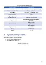
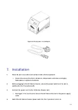
Page 12: ... protection Class I Degree of protection IP20 Maximum run time 59 minutes and 59 seconds Safety features Interlock thermal cut out temperature regulation Unit dimensions Width 210 mm Height 228 mm Depth 310 mm Tray dimensions 150 mm Ø Fuses 1 A slow blow Weight 5 45 kg 6 System Components The UV Ozone Cleaner comprises two items UV Ozone Cleaner unit Figure 6 1 Power supply cord Figure 6 2 Figure ...

Page 13: ...xtremes and highly flammable or explosive materials 2 Before plugging in the UV Ozone Cleaner ensure the power switch on the unit is switched to the 0 position off 3 Connect the power cord to the UV Ozone Cleaner unit i See Figure 7 1 to see how to connect the UV Ozone Cleaner to the power supply cable 4 Switch the UV Ozone Cleaner power switch to the I position to turn on ...

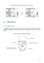
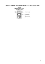
Page 14: ...d cable 8 Operation 8 1 Overview A top down view of the UV Ozone Cleaner is shown in Figure 8 1 with all the relevant components highlighted Figure 8 2 shows the power cord socket fuse socket and the power switch Figure 8 1 Components of the UV Ozone Cleaner ...

Page 15: ...15 Figure 8 2 UV Ozone power switch fuse socket and power socket position on the back panel ...

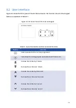
Page 16: ...pad Table 8 1 Operational buttons and their associated functions Button Function Starts operation for the Set Time programmed Terminates the running program and resets the Set Time to zero Increase the set time by 1 minute Decrease the set time by 1 minute Increase the set time by 10 seconds Decrease the set time by 10 seconds Increase the set time by 1 second Decrease the set time by 1 second ...

Page 17: ...he desired Set Time and press the start button see section below 4 Once the program has finished open the tray door and remove your sample 8 4 Program Operation WARNING High voltage The UV Ozone Cleaner is mains powered Make sure the unit is connected to a grounded power outlet Ensure the area around the back of the unit is kept clear It is good practice to keep any cables around the unit in a tid...

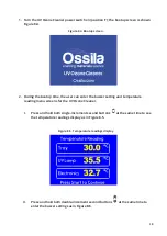
Page 18: ...the buzzer setting and temperature reading menu screens for the UV Ozone Cleaner I Press and hold both single increment second buttons at the same time to see the temperature readings display as in Figure 8 5 Figure 8 5 Temperature readings display II Press and hold both double increment second buttons at the same time to enter the buzzer settings as in Figure 8 6 ...

Page 19: ...er settings menu 3 To exit the Settings page press the START button to proceed to continue 4 The user must read the caution message and press START to enter the main screen of the UV Ozone Cleaner as shown in Figure 8 7 Figure 8 7 Caution screen 5 Modify the Set Time using the Minute MIN and Second SEC buttons on the keypad The maximum value of the timer is 59 min 59 secs as shown in Figure 8 8 ...

Page 20: ...Set Time the one note buzzer will sound indicating the program has finished III While the program is running the user can stop the program by pressing the STOP button This will also reset the Set Time to 00 00 Figure 8 9 Set Time screen 7 The fan in the unit will turn on when the cleaning program is started and will turn off once the STOP button is pressed if the Tray Temperature is below 27 C If ...

Page 21: ...temperature value a high temperature warning will appear on the screen Table 8 2 shows the different warnings for this unit for given temperatures The error code that is displayed when the tray or electronics sensor exceeds 60 C indicates which sensor is at a high temperature and is used for troubleshooting III Temperature Error If one of the temperature sensors gives an error reading a warning as...

Page 22: ...22 Table 8 2 High temperature warning Warning Display HIGH TEMP if tray or lamp is 50 C or electronics 45 C VERY HIGH TEMP if tray or electronics is 60 C Figure 8 11 Temperature error warning ...

Page 23: ...faults that occur outside the warranty period 9 3 Storage Conditions The UV Ozone Cleaner should be kept in dry conditions away from direct sources of heat or sunlight and in such a manner as to preserve the working life of the instrument 10 Troubleshooting Problem Possible cause Action No power display a The power switch on the unit is in the OFF position b The power supply may not be connected p...

Page 24: ...tray door has not been closed properly TRAY OPEN will display a Ensure the tray door is fully closed The drawer should hold firmly in position when this is the case Continuous buzzer a Error in temperature reading UV Ozone Cleaner temperature is extremely high a Check the temperature reading by entering the settings mode referred to Section 8 4 If the temperature is extremely high turn the unit OF...

Reviews: