background image

18

The Ossila Source Measure Unit is designed to work with any network that supports DHCP. When the 
ethernet cable is plugged in, the unit will automatically detect and identify the network and register itself 
within a few seconds.

For most networks, the unit will need no further work – simply plug in and wait for the DHCP to work, and it is 

ready to go. However, there are two situations where more steps are required:

(I) Networks Requiring Registering Devices

Some large corporate networks (such as universities) have increased security levels and will only allow 
“known/registered” devices onto the network. If this is the case for your network, you will need to register 

the MAC address first. After this, the unit should be allowed on the network and will work as normal via 

DHCP (fully automatically from this point with no intervention). Many institutions have their own registration 
systems for computers and printers, and usually have online instructions on how to register a device. If 
needed, the MAC address of the unit can be obtained by connecting to it with the Front Panel software  
over USB.

(II) Static IP Networks 

For a network without DHCP support, a static IP address must be set manually. This can be done by following 

these steps:

1.  Connect the Source Measure Unit to a PC using a USB cable.
2.  Disable the DHCP client of the device using the command “

eth0 set dhcp false

”.

3.  Set the IP address and other network parameters using the command “

eth0 set network ip-address 

subnet-mask gateway-ip dns-ip

”.

4.  Save the changes to the board so that they are loaded when the device powers on using the  

command “eth0 save network”.

5.  Disconnect the USB cable, then connect the Ethernet cable and the device should connect after  

a few seconds.

Alternatively, an external network router that supports DHCP can be used to connect to a static IP network.

1. 

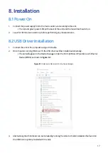
Run the file ‘Ossila-Front-Panel-Installer-vX-X-X-X.exe’ on the USB memory stick provided.

2.  Follow the on-screen instructions to install the software.

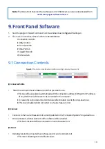
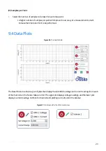
8.3 Connecting to a Network

8.4 Front Panel Software Installation

Summary of Contents for UNIT-X200

Page 1: ...USERMANUAL Manual Version 2 0 E Product Code P2005A Product Version 2 0 Firmware Version 2 4 Software Version 1 2 SOURCE MEASURE UNIT X200 ...

Page 2: ...twareRequirements 9 5 Unpacking 10 5 1PackingList 10 5 2DamageInspection 10 6 Specifications 10 6 1SpecificationConditions 10 6 2SourceMeasureUnits SMU1andSMU2 11 6 3Voltmeter Vsense1andVsense2 14 6 4MeasurementNon Linearity 14 6 5Shutter Trigger 14 6 6PhysicalSpecifications 15 7 SystemComponents 15 8 Installation 17 8 1PowerOn 17 8 2USBDriverInstallation 17 8 3ConnectingtoaNetwork 18 8 4FrontPane...

Page 3: ...ConnectionControls 19 9 2UtilityControls 20 9 3FrontPanel 21 9 4DataPlots 23 9 5LoggedData 25 9 6IVCurve 26 10 AdvancedMeasurements 29 11 Troubleshooting 30 12 Relatedproducts 31 12 1RelatedConsumables 31 12 2RelatedEquipment 31 ...

Page 4: ...ocontrolinstrumentsisakeyskillforexperimentalscientistsandengineers Wehavedesigned theSMUsothatnomatterwhatyourskilllevelis youcanaccessaffordable preciseinstrumentation 1 1Features DualSourceMeasure SMU channels DualVoltmeterchannels 10Vsource Upto 200mAsource sinkcurrentperchannel Fivesoftwarecontrolledcurrentranges 10nA 200mA Shuttercontrolortriggerinput SerialandI2 Cextension PCsoftwarefrontpa...

Page 5: ...declarethattheDoCisissuedunderoursoleresponsibility andbelongstothefollowingproduct Product SourceMeasureUnit X200 P2005A2 Serialnumber P2005A2 xxxx Objectofdeclaration SourceMeasureUnit X200 P2005A2 Theobjectofdeclarationdescribedaboveisinconformity withtherelevantUnionharmonisationlegislation EMCDirective2014 30 EU RoHSDirective2011 65 EU Signed Name DrJamesKingsley Place Sheffield Date 01 10 20...

Page 6: ...τότηταςΕΕ Κατασκευαστής OssilaLtd SolproBusinessPark WindsorStreet S47WD ΗνωμένοΒασίλειο ΔηλώνουμευπεύθυναόnοαναφερόμενοςεξοπλισμόςσυμμορφώνεταιμετησχεnκήνομοθεσίαεναρμόνισηςτηςΕΕπουυπάρχει σnςπροηγούμενεςσελίδεςτουπαρόντοςεγγράφου Español DeclaracióndeconformidadUE Fabricante OssilaLtd SolproBusinessPark WindsorStreet S47WD ReinoUnido Declaramosbajonuestraúnicaresponsabilidadqueelsiguienteproduct...

Page 7: ...dsorStreet S47WD ReinoUnido Declarasobsuaexclusivaresponsabilidadequeoequipamentoindicadoestáemconformidadecomalegislaçãodeharmonização relevantedaUEmencionadana s página s anterior es destedocumento Română DeclaraţiedeconformitateUE Producător OssilaLtd SolproBusinessPark WindsorStreet S47WD RegatulUnit DeclarăpeproprierăspunderecăechipamentulprezentatesteînconformitatecuprevederilelegislaţieiUEd...

Page 8: ...ppliedwitha24VDC 2Apoweradapterwithapowercordforthecountryofpurchase in accordancewithEuropeanCommissionregulationsandBritishStandards Useofanyotherelectricalpower cables adaptors ortransformersisnotrecommended 3 3HazardIcons Thefollowingsymbolscanbefoundatpointsthroughoutthemanual Noteandreadeachwarningbefore attemptinganyassociatedoperationsassociatedwithit Table3 1 Hazardwarninglabelsusedinthis...

Page 9: ... Thewarrantywillbeinvalidatedif ModificationorservicehasbeencarriedoutbyanyoneotherthananOssilaengineer Theunithasbeensubjectedtochemicaldamagethroughimproperuse Theunithasbeenoperatedoutsidetheusageparametersstatedintheuserdocumentation associatedwiththeunit Theunithasbeenrenderedinoperablethroughaccident misuse contamination improper maintenance modification orotherexternalcauses TheOssilaSMUisc...

Page 10: ...ntrolledor controltheunit 6 Specifications 5 Unpacking 5 2DamageInspection 6 1SpecificationConditions Examinethecomponentsforevidenceofshippingdamage Ifdamagehasoccurred pleasecontactOssila directlyforfurtheraction Theshippingpackagingwillcomewithashockindicatortoshowiftherehasbeen anymishandlingofthepackageduringtransportation ThespecificationsandinformationinthisdocumentarefortheOssilaSourceMeas...

Page 11: ...itingtheoutputorlowimpedancescausingasmalldropinvoltage Eachsourcemeasureunithasmanuallyselectablerangessothatbothhighandlowcurrentscanbe measuredaccurately 6 2 1PowerSpecifications TheunitisspecifiedforamaximumoperationpowerasinTable6 1 Figure6 1showsthefour quadrant safeoperationzoneoftheunit Table6 1 DCpowerspecification Figure6 1 Thefour quadrantsafeoperationzone PowerperSMUchannel continuous ...

Page 12: ...geoftheSMUwillbeset to0V Thisisameasuretoreducethepossibilityofdamagingtheunitduetoexcessivevoltagesorcurrents Thevoltageandcurrentlimitscanbechangedprogrammatically buttheyshouldnotbeincreasedpastthe defaultvaluesasthiswillincreasethepossibilityofdamagingtheunit 6 2 2MeasurementSpeed TheOssilaSourceMeasureUnitutilisesahigh speed 24 bitnoLatency Σ ADC Itprovidestenspeed resolutioncombinations 6 9H...

Page 13: ...tions Warning DoNOTattachexternalvoltagesourcestoeitherSMUmoduleasthismayresultin damagetotheunit 6 2 4CurrentMeasurementSpecifications ThecurrentmeasurementoftheOssilaSourceMeasureUnitisspreadover5ranges Eachrangehas adifferentmaximumcurrent accuracy andresolution Astherangenumberincreases themaximum measurablecurrentdecreases buttheaccuracyandresolutionincrease Table6 4 Currentmeasurementspecifi...

Page 14: ...laSourceMeasureUnitiskeptwellbelowthe measurementaccuracyofeveryrange Suchnon linearityiscommonduetodifferentamplificationstages andanaloguedigitalconversionprocesses TheShutter Triggercanbeusedeitherasaninputoranoutput Itcanbeusedtosendatriggersignalto otherinstrumentsorconfiguredtowaitforatriggerfromotherinstruments ThevoltageleveloftheShutter Triggeris5voltsandcansourceandsinkupto30mAofcurrent ...

Page 15: ...gger Connectivity USBandEthernet Dimensions Width 125mm Height 55mm Depth 185mm Weight 0 55kg Powersupply 24VDC 2A 6 6PhysicalSpecifications 7 SystemComponents TheOssilaSourceMeasureUnitP2005Acomprisesthreeitems theOssilaSourceMeasureUnit Figure7 1 poweradapter Figure7 2 andtheOssilaFrontPanelsoftware Figure7 3 Figure7 1 SourceMeasureUnit ...

Page 16: ...16 Figure7 3 TheOssilaFrontPanelPCsoftware Figure7 2 The24VDCpoweradapter ...

Page 17: ...usingaUSBcable 2 OncomputersrunningWindows10 theUSBdriverswillbeinstalledautomatically I TheunitwillappearintheDeviceManagerunderthePorts COM LTP sectionasUSBSerial Device COMX asshowninFigure8 1 Figure8 1 OssilaSourceMeasureUnitintheDeviceManager 8 Installation 8 1PowerOn 8 2USBDriverInstallation 3 Alternatively theUSBdriverscanbeinstalledbyrunningthe32 bitor64 bitinstallationfilefoundon theUSBme...

Page 18: ...nters andusuallyhaveonlineinstructionsonhowtoregisteradevice If needed theMACaddressoftheunitcanbeobtainedbyconnectingtoitwiththeFrontPanelsoftware overUSB II StaticIPNetworks ForanetworkwithoutDHCPsupport astaticIPaddressmustbesetmanually Thiscanbedonebyfollowing thesesteps 1 ConnecttheSourceMeasureUnittoaPCusingaUSBcable 2 DisabletheDHCPclientofthedeviceusingthecommand eth0setdhcpfalse 3 SettheI...

Page 19: ... I ConnectedSMUs SelecttheconnectedSourceMeasureUnitthatyouwanttouse I Thisboxwillbepopulatedautomaticallywiththeconnectionaddress COMportorIPaddress ofanyOssilaSourceMeasureUnitsconnectedtothecomputer II Torescanforconnectedunits clickthebluerefreshbuttonnexttothedrop downbox III ThisboxisdisabledwhilstconnectedtoaSourceMeasureUnit II Connect ConnectstotheSourceMeasureUnitcurrentlyselectedinthe C...

Page 20: ... I Theshutteroutputs5VDCwhenswitchedon IV LogData Recordsthevaluesofallchannelsintheloggeddatatable alongwiththecurrentdateandtime I Records0 0forchannelsthatareswitchedoff V SaveLiveData Toggleswhetherdatawillbecontinuouslysavedwhileachannelisswitchedon I Thedatawillbesavedtothecommaseparatedvalue csv ortext txt filesetinthe SaveData Path field VI SaveDataPath Setsthedirectoryandfilenameforsaving...

Page 21: ... SMU2 Vsense1 andVsense2 EachSMUpanelcontainsanon offtogglebutton voltage left andcurrent right measurementdisplays andthesettings whicharedetailedbelow I SetVoltage SetstheoutputvoltageoftheSMU maximumof 10V 9 3FrontPanel Figure9 3 TheFrontPaneltab Figure9 4 ControlandoutputpanelfortheSMUs ...

Page 22: ...racyofameasurementbutwill increasethetimetakenforittobeperformed IV VoltageLimit SetsthemaximumvoltagethattheSMUcansource default10 5V I Ifthemeasuredvoltageisabovethevoltagelimit theoutputvoltagewillbesetto0V V CurrentLimit SetsthemaximumcurrentthattheSMUwillmeasure I Ifthemeasuredcurrentisabovethesetcurrentlimit therangewillautomaticallybeswitchedto Range1topreventdamagetotheSMU II IftheSMUisalr...

Page 23: ...dings andthelowerplot displayscurrentreadings Controlsforchannelsandplottingcanbefoundinthesidebar 9 4DataPlots Figure9 6 TheDataPlotstab Figure9 7 ControlpanelsfortheSMUsandVsenses VI SamplesperPoint Selectthenumberofsamplestobetakenforeachdatapoint I Ahighernumberofsamplesperpointwillimprovetheaccuracyofameasurementbutwill increasethetimetakenforittobeperformed ...

Page 24: ... SaveData Dataintheplotscanbesavedbyclickingthegreensavebutton Thisopensadialogboxtonavigatetothedesiredsavedirectoryandnamethefile I Thedesiredfiletype commaseparatedvalue csv ortext txt canbeselectedusingthedrop downboxtotherightofthefilenamefield III ClearPlots Theplotscanbeclearedbyclickingredclearbutton IV GraphDisplayControls Bydefault theplotswillautomaticallyscaletheaxesofthegraphtodisplay...

Page 25: ...cordedwhenthe LogData buttonisclicked Therearetwobuttonstotheleftofthetable I SavingData Datainthetablecanbesavedbyclickingtheuppergreenbutton Thisopensadialogboxtonavigatetothedesiredsavedirectoryandnamethefile I Thedesiredfiletype commaseparatedvalue csv ortext txt canbeselectedusingthe drop downboxtotherightofthefilenamefield ...

Page 26: ...deletedbyhighlightingatleastonecellineachrowfordeletion Theneither I Right clickonthehighlighteddataandselect DeleteRow fromthemenu II Alternatively thekeyboardshortcutDeletecanbeused Aconfirmationboxwillappearbeforeanydataisdeleted 9 6IVCurve Figure9 10 TheIVCurvetab TheIVCurvetabcontainscontrolsforperformcurrent voltage IV measurements Themeasurementcanbe customisedwiththefollowingsettings I Vol...

Page 27: ...ostartthecurrent voltagemeasurement I Thiscanbesetbetween 10Vand 10V V EndVoltage Setthevoltageinvoltsatwhichtoendthecurrent voltagemeasurement I Thiscanbesetbetween 10Vand 10V VI VoltageIncrement Setthestepsizeinvoltsforchangingthevoltageduringcurrent voltagemeasurement VII VoltageSettleTime Setthetimeinsecondsbetweenapplyingavoltageandmeasuringthecurrent I Thishasamaximumof10seconds VIII Hystere...

Page 28: ...edvalue csv ortext txt canbeselectedusingthe drop downboxtotherightofthefilenamefield II ClearPlot Theplotcanbeclearedofalldatabyclickingthereddeletebuttontotherightoftheplot III GraphDisplayControls Bydefault theplotswillautomaticallyscaletheaxesofthegraphtodisplayallthedatawithinit Theviewcan becontrolledmanuallyusingthefollowingmousecontrols Left Middleclickanddrag pantheaxes Rightclickanddrag ...

Page 29: ...urementthatisnotcoveredbytheFrontPanelsoftware youcancontrolthe SourceMeasureUnitdirectlyusingavarietyofprogramminglanguages Moreinformationandtheavailable commandscanbefoundintheProgrammingDocumentation downloads ossila com manuals source measure unit programming documentation v2 4 pdf ...

Page 30: ...leisfirmlypluggedinatbothends b TryconnectingthesystemtoadifferentUSBport onthecomputer c Tryinstallingorreinstallingthedrivers theycanbe downloadedfromtheaddressgivenintheSoftware Installationsection d TryusingadifferentUSBcable anyshouldwork and contactOssilaifnecessary Cannotconnecttothe systemviaNetwork a TheMACaddressofthesystemisnot registeredwiththeinternalnetwork b TheEthernetcablemaynotbe...

Page 31: ...asy An easy to use tool for the rapid measurement of sheet resistance resistivity and conductivity of materials Product codes T2003B2 Product code T2004 T2005 Product code P2011A1 Product code T2001A3 Flattiptweezers SubstrateCleaningRack ITOSubstrates FTOCoatedGlass Substrates Provides a good substrate grip without scratching Holds 20 substrates for a variety of processing techniques Our range of...

Page 32: ......

Reviews: