


Page 4
Slot
A single chassis position consisting of a backplane connector and
its associated module-guides.
“A” Link
A backplane slot-to-slot connection that provides Ethernet connectivity
between adjacent slots (sometimes referred to as “A” Backplane Link).
“A” Port
An interface on a module capable of Ethernet traffic via the
backplane’s “A” Link.
“B” Link
A backplane slot-to-slot connection that provides Ethernet connectivity
between adjacent slots (sometimes referred to as “B” Backplane Link).
“B” Port
An interface on a module capable of Ethernet traffic via the
backplane’s “B” Link.
1.2 Mechanical Description
The 5-Module chassis consists of any combination of one or two AC or DC power
supplies. As can be seen from the model table on the previous page, four models
have been pre-configured with one and two power supplies. Any other combination
of AC and DC power supplies are permitted. The power supplies provide power to
the chassis’ 5 backplane connectors.
1.3 Backplane Architecture
The chassis features 5 module slots numbered 1 (left-most positioned slot) through
5 (right-most positioned slot). As modules are inserted into the chassis slots, they
are seated into the slot connectors.
The “A” and “B” Links provide Ethernet connectivity between adjacent slots.
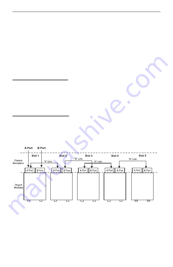
Fig. 2 5-Module Backplane Architecture
Fig. 2 Depicts the chassis’ backplane architecture including the “A” and “B” Links.
The “A” Links connect between odd numbered slots on the left to even numbered
slots on the right (i.e. 1-2, 3-4).
The “B” Links connect between the even numbered slots on the left to odd numbered
slots on the right (i.e. 2-3, 4-5).


