background image

Page 5

When modules with “A” and “B” Port capabilities are inserted into adjacent chassis
slots, they can connect to each other via the backplane links and create flexible
network architectures that meet the user’s requirements.

Note that not all modules support and have backplane ports. To find out about
each specific module’s backplane port configuration, refer to the specific
module’s documentation.

This chassis architecture facilitates a variety of applications including unmanaged,
out-of-band managed, in-band managed and multi-port configurations.

1.4 Application Examples

1.4.1 Out-of-Band Managed 10/100Mbps Converter Application

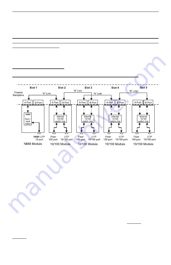
Fig. 3  Out-of-Band Managed 10/100Mbps Converter Application

Fig. 3 depicts an out-of-band managed 10/100 converter application. In this application,
which is typical for a Central Office (CO) or a network core, a 5-Module chassis is loaded
with 10/100 UTP to fiber converters that convert UTP cabling originating at a core switch
to fiber and distributing the fiber in a star configuration to different customers.

Out-of-band management is desirable in this application since it facilitates secure
monitoring, configuration and trap notification of a large number of converter modules in
the chassis.

This application uses four 10/100 modules for UTP to fiber conversion and a Network
Management Module (NMM) for management. All modules are plugged into the
5-Module chassis.

The 10/100 converter module is designed as a 4-port switch with two front-plane Ethernet
ports (100BASE-FX fiber and 10/100BASE-T/TX UTP) and two 10/100 Ethernet backplane
ports (“A” and “B” Ports). In this application, the “A” and “B” Ports are disabled to provide
isolation between the modules.

The NMM module features a 10Mbps Ethernet “A” Port. In this application, its “A” port is
disabled and connectivity to the management network is performed via the NMM module’s
front-plane Ethernet port.

It is important to emphasize that in this type of application, the “A” and “B” Ports of all of

Summary of Contents for iConverter 8090-0

Page 1: ...Page 1 140 Technology Dr 500 Irvine CA 92618 USA Phone 949 250 6510 Fax 949 250 6514 iConverter 5 Module Power Chassis User Manual...

Page 2: ...rranty period Omnitron will at its option repair or replace a product which is proven to be defective For warranty service the product must be sent to an Omnitron designated facility at Buyer s expens...

Page 3: ...ne A printed circuit board which is permanently mounted inside the chassis and is populated with receptacle connectors into which modules are inserted Module An iConverter plug in card positioned into...

Page 4: ...can be seen from the model table on the previous page four models have been pre configured with one and two power supplies Any other combination of AC and DC power supplies are permitted The power sup...

Page 5: ...to fiber converters that convert UTP cabling originating at a core switch to fiber and distributing the fiber in a star configuration to different customers Out of band management is desirable in this...

Page 6: ...onverter Switch Application Fig 4 In Band Managed 10 100Mbps Converter Switch Application Fig 4 depicts a 5 Module chassis with four modules plugged into adjacent back plane slots In this application...

Page 7: ...d or multi unit rack assembly the operating ambient temperature of the rack must not exceed the maximum rated 50 degrees C temperature Installation of the equipment should be such that the air flow in...

Page 8: ...d WARNING REGARDING EARTHING GROUND o o o o This equipment shall be connected to the DC supply system earthing electrode conductor or to a bonding jumper from an earthing terminal bar or bus to which...

Page 9: ...ing mount and attach the chassis after the mounting brackets are installed to the rack using the appropriate rack mounting screws not provided Locate the DC circuit breaker and switch the circuit brea...

Page 10: ...y is not present Blinking LED indicates that a power supply is installed but does not supply power because it is not properly connected to a power source or because it is faulty Once you determine tha...

Page 11: ...he circuit breaker to the OFF position Remove the DC power cables of the faulty power supply from the iConverter power supply unit Using a screwdriver loosen the 2 thumb screws securing the power supp...

Page 12: ...Model Number 8220 1 1 PS 8220 2 2 PS 8226 1 1 PS 8226 2 2 PS 8225 1 1 PS 8225 2 2 PS Module Capacity 5 Power Supply Capacity 1 2 Power Supplies Power Requirements typical 100 to 240VAC 50 to 60Hz 0 5...

Reviews: