background image

Page 8

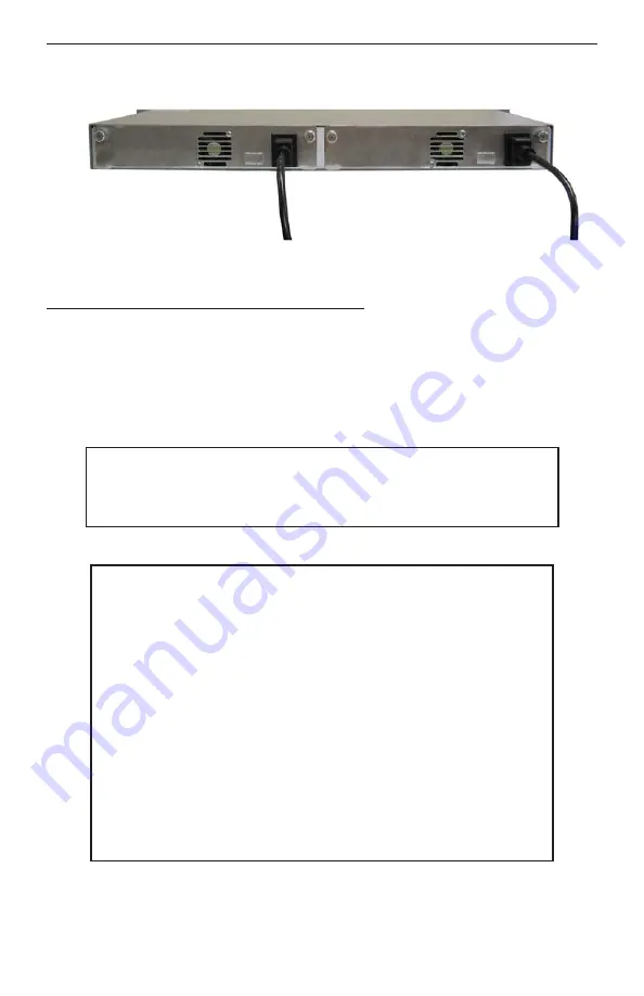
Fig. 5   5-Module Chassis with two Installed AC Power Supplies

3.3 DC Powered Chassis Site Preparation

†

Power source should be available within 5 ft. of the chassis. The over current
protection for the connection with centralized DC shall be provided in the building
installation and shall be a UL listed breaker rated at 15 Amps, and installed per
the National Electrical Code, ANSI/NFPA-70.

†

The 8225-1 and 8225-2 require 36-60VDC/0.7 Amps power. The 8226-1 and 8226-2
require  18-36VDC/1.4 Amps power.  Appropriate overloading protection should be
provided on all DC power source outlets utilized.

WARNING:

Only a DC power source that complies with

safety extra low voltage (SELV) requirements can be
connected to the DC-input power supply.

†

When rack-mounting this equipment, the rack should be appropriately earth-grounded.

WARNING REGARDING EARTHING GROUND:

o

o

o

o

This equipment shall be connected to the DC supply

system earthing electrode conductor or to a bonding
jumper from an earthing terminal bar or bus to which the
DC supply system earthing electrode is connected.

This equipment shall be located in the same immediate

area (such as adjacent cabinets) as any other equipment
that has a connection between the earthed conductor of
the same DC supply circuit and the earthing conductor,
and also the point of earthing of the DC system. The DC
system shall not be earthed elsewhere.

The DC supply source is to be located within the same

premises as this equipment.

There shall be no switching or disconnecting devices in

the earthed circuit conductor between the DC source and
the earthing electrode conductor.

†

The operating temperature of this equipment is 0 to 50 degrees C. If installed in
a closed or multi-unit rack assembly, the operating ambient temperature of the
rack must not exceed the maximum rated 50 degrees C temperature.

Summary of Contents for iConverter 8090-0

Page 1: ...Page 1 140 Technology Dr 500 Irvine CA 92618 USA Phone 949 250 6510 Fax 949 250 6514 iConverter 5 Module Power Chassis User Manual...

Page 2: ...rranty period Omnitron will at its option repair or replace a product which is proven to be defective For warranty service the product must be sent to an Omnitron designated facility at Buyer s expens...

Page 3: ...ne A printed circuit board which is permanently mounted inside the chassis and is populated with receptacle connectors into which modules are inserted Module An iConverter plug in card positioned into...

Page 4: ...can be seen from the model table on the previous page four models have been pre configured with one and two power supplies Any other combination of AC and DC power supplies are permitted The power sup...

Page 5: ...to fiber converters that convert UTP cabling originating at a core switch to fiber and distributing the fiber in a star configuration to different customers Out of band management is desirable in this...

Page 6: ...onverter Switch Application Fig 4 In Band Managed 10 100Mbps Converter Switch Application Fig 4 depicts a 5 Module chassis with four modules plugged into adjacent back plane slots In this application...

Page 7: ...d or multi unit rack assembly the operating ambient temperature of the rack must not exceed the maximum rated 50 degrees C temperature Installation of the equipment should be such that the air flow in...

Page 8: ...d WARNING REGARDING EARTHING GROUND o o o o This equipment shall be connected to the DC supply system earthing electrode conductor or to a bonding jumper from an earthing terminal bar or bus to which...

Page 9: ...ing mount and attach the chassis after the mounting brackets are installed to the rack using the appropriate rack mounting screws not provided Locate the DC circuit breaker and switch the circuit brea...

Page 10: ...y is not present Blinking LED indicates that a power supply is installed but does not supply power because it is not properly connected to a power source or because it is faulty Once you determine tha...

Page 11: ...he circuit breaker to the OFF position Remove the DC power cables of the faulty power supply from the iConverter power supply unit Using a screwdriver loosen the 2 thumb screws securing the power supp...

Page 12: ...Model Number 8220 1 1 PS 8220 2 2 PS 8226 1 1 PS 8226 2 2 PS 8225 1 1 PS 8225 2 2 PS Module Capacity 5 Power Supply Capacity 1 2 Power Supplies Power Requirements typical 100 to 240VAC 50 to 60Hz 0 5...

Reviews: