Page 9
Installation of the equipment should be such that the air flow in the front and
back of the unit is not compromised or restricted.
Installing this equipment into a rack in such a way as to make it unstable
may
cause injury or death
. Always make sure that the rack you are installing this
equipment into is properly secured, stable, balanced and designed to carry the
weight and weight distribution of this equipment.
Never use this equipment to carry any weight except its own. Never use it as a
shelf to support the weight of other equipment.
3.4 DC Powered Chassis Mounting and Cabling
If rack mounting the chassis to a 19” standard rack, first attach the two enclosed
“L” shaped rack mounting brackets to the chassis using the enclosed screws.
If rack mounting, mount and attach the chassis (after the mounting brackets are
installed) to the rack using the appropriate rack mounting screws (not provided).
Locate the DC circuit breaker and switch the circuit breaker to the OFF position.
Prepare a power cable using a three conductor insulated wire (not supplied) with a
14 AWG gauge. Cut the power cable to the length required.
Strip approximately 3/8 of an inch of insulation from the power cable wires.
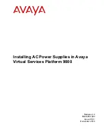
Connect the power cables to the
iConverter
Chassis by fastening the stripped ends
to the DC power connector.
WARNING:
Note the wire colors used in making the positive, negative and ground
connections. Use the same color assignment for the connection at the circuit breaker.
Connect the power wires to the circuit breaker and switch the circuit breaker ON. The
fans should immediately begin to run and any installed
iConverter
modules will
illuminate the power LEDs.
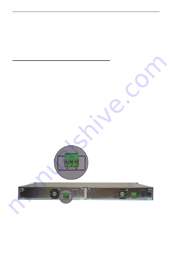
Fig. 6 5-Module Chassis with two Installed DC Power Supplies