For versions ≥ V2.4X it is possible to use pressure sensors that communicate via
Modbus.
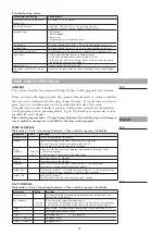
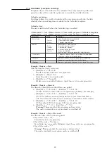
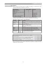
If pressure sensors that communicate via Modbus master are used, these are connec-
ted via the Modbus RTU/RS485 connection. It will then no longer be possible to use
the built-in Modbus RTU/slave for BMS, but you can still use Modbus TCP/IP to
connect to BMS.
If the property’s BMS requires Modbus RTU you can use an external communication
module for Modbus RTU. See chapter 12.7.
DESIGNATIONS AND MEASURING RANGES OF THE PRESSURE SENSORS, GP1, GP2
This model does not need any extra expansion module, and therefore does not require
multiple I/O’s. . The signal for each pressure transmitter goes via data bus communi-
cation.
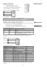
Pressure sensors used is QBM68.
These pressure sensors are available with pressure ranges 1250 Pa or 2500 Pa.
QBM68 is also available for double sensors in a unit (enclosure), with the first sensor
marked P1 and the second sensor marked P2.
The following variants are possible:
Designation
P1 pressure range
P2 pressure range
Modbus/0–10V signal
QBM68.1200
0-1250Pa
---
Yes/Yes
QBM68.1212
0-1250Pa
0-1250Pa
Yes/Yes
QBM68.2500
0-2500Pa
---
Yes/Yes
QBM68.2512
0-2500Pa
0-1250Pa
Yes/Yes
QBM68.2525
0-2500Pa
0-2500Pa
Yes/Yes
SETTINGS AND CONNECTIONS
ASSEMBLY
To obtain the desired IP rating, the differential pressure sensor must be mounted ver-
tically (connection fittings downward). The connection fittings must also be located
higher than the measuring tube at the air duct.
When the connection fittings are pointed upward, or if these are lower than the mea-
suring tubes, condensation water can be collected in the sensor and cause damage.
45
10. Modbus pressure sensor for pressure regulation
Important!
PRESSURE SENSOR QBM68
1 2 3 4 5 6 7 8
ON
1 2 3 4
ON
A
B
Important!
10.1
10.2
10.3
1270466_utg3_HERU_400_1200_eng.indd 45
2020-10-28 11:59:48
1270466_utg3_HERU_400_1200_eng.pdf 45
2020-10-28 12:04:20


