46
PRESSURE REGULATION, ADDRESSING OF PRESSURE SENSOR
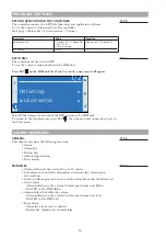
When using Modbus signal for pressure sensors, the pressure range does not need to
be adjusted. Modbus handles this via the data signal. The measuring range is only used
when the 0-10 V signal is used.
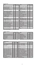
Description I/O designation
Type of function
Pressure sensor unit
I/O type
Pxxx
x40x
xxx1
Supply air pressure, GP1
QBM68.2525
P401
Pressure
MB address 40
1=P1
Extract air pressure, GP2
QBM68.2525
P402
Pressure
MB address 40
2=P2
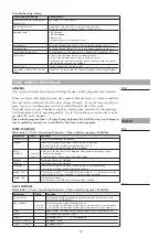
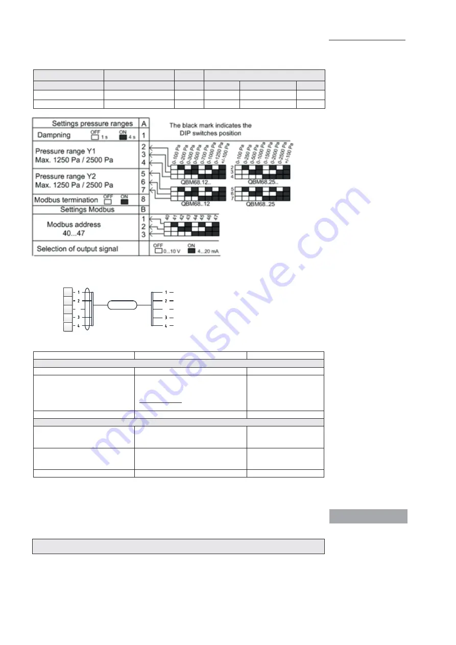
See previous image regarding to A setting pressure range & B settings Modbus.
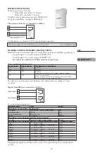
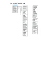
Connected as follows:
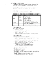
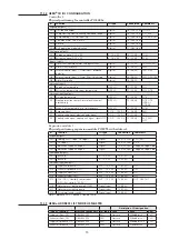
For activation/configuration:
Parameter name
Area
Select
Main index > Configuration > Configuration 1
Expansion module
No, One, Two
No
Fan regulation type
Fixed frequency, pressure regulation,
flow regulation, supply air slave, extract
air slave
(Direct, Direct FO not applicable to
HERU
®
CX )
Select Pressure regulation
Restart
√, Execute
Execute
Main index > Configuration > Config. IOs > Pressure/ Flow
Supply air pressure
Pos: Factor: Area:
Com 500 Pa*
Type: P401
Select type: P401
Extract air pressure
Pos: Factor: Area:
Com 500 Pa*
Type: P402
Select type: P402
Restart
√, Execute
Execute
*The pressure sensor’s max measuring range (500 Pa) is only active at 0-10 V signals from the
pressure sensor. With Modbus, this value is not active, i.e. the measuring value is automatically
sent via Modbus.
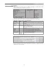
The modbuster termination must be switched on when using pressure sensors that are not
controlled via 0-10V.
995010040 contains a QBM68.2525, which contains two sensors, P1 & P2, which are used for
pressure regulation. Depending on which address you give the sensor, it will be used for the
relevant function, provided that the function is enabled during configuration.
Pressure sensor Climatix MB with 10 m cable
..................... Art.no 995010040
10.4
94
95
HERU® CX
AHU
QBM68.xxx
96
99
100
SH
SH
A+
B-
Ref.
0V
24V
Note!
1270466_utg3_HERU_400_1200_eng.indd 46
2020-10-28 11:59:48
1270466_utg3_HERU_400_1200_eng.pdf 46
2020-10-28 12:04:21


