


110 / 120
2017-11-03
Climatix HERU® 400-2400
SERVICE HERU®
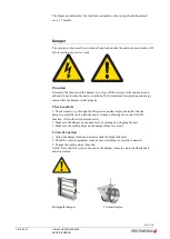
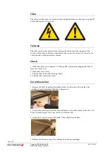
Heating coil
The safety switches must be switched off and locked after the unit has been switched off
before starting any service work.
Function
The air heater uses water to heat the supply air to the desired outgoing temperature. The
heater consists of a number of copper pipes with aluminium slats. For circulation and
regulation of the water, the heater is usually equipped with a shunt group. To protect the
heater from freezing, a strap-on frost protection sensor is mounted on the collection pipe.
Check
1. That the front surface of the coil is not dirty.
2. That the pump is running and that the water is circulating and has the correct temperature
for the season.
3. Function of frost protection
4. That the slats are intact (not damaged).
5. That the coil is not damaged and is not leaking.
Corrective action
1. Clean with a vacuum cleaner fitted with a soft brush.
2. Check the pump for damage. Check sensor function.
3. Make sure that the strap-on sensor is correctly positioned. Replace the strap-on sensor if
necessary.
4. Adjust the slats with a “slat comb”.
5. Turn off the water and empty the system through the coil’s drain valve. Change the coil.
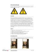
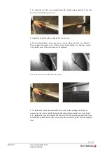
Pull out the coil.
1. Turn off the unit via the control panel and place the
main power switch in position 0.
2. Switch off the shunt and close the stop valves.
3. Empty the system through the coil’s drain valve.
4. Remove the coil’s screw caps in the unit.
5. Pull out the coil.
Summary of Contents for HERU 400-2400 S
Page 1: ...U S E R M A N U A L E N H E R U 4 0 0 2 4 0 0 T S HERU T HERU S...
Page 2: ......
Page 14: ...14 120 Climatix HERU 400 2400 2018 02 13 Scope of assembly installation instructions...
Page 45: ...45 120 2018 02 13 Climatix HERU 400 2400 External components basic unit...
Page 97: ...97 120 2018 02 13 Climatix HERU 400 2400 Miscellaneous Menu structure Menu overview...
Page 98: ...98 120 Climatix HERU 400 2400 2018 02 13 Miscellaneous Start page Main index Unit...
Page 104: ...104 120 Climatix HERU 400 2400 2018 02 13 SERVICE HERU...
Page 111: ...111 120 2018 02 13 Climatix HERU 400 2400 SERVICE HERU...
Page 118: ...118 120 2017 11 03 Climatix HERU 400 2400 Troubleshooting...
Page 119: ......
Page 120: ......


