


12 / 120
Climatix HERU® 400-2400
2018-02-13
Scope of assembly/installation instructions
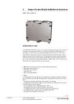
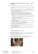
ASSEMBLY AND INSTALLATION INSTRUCTIONS
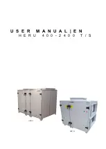
HERU
®
400-2400 T/S
The base of the HERU T/S unit must be even and stable. Note and take into account the
unit’s weight.
1. Always lift the unit using a pallet jack or truck with forks at least as long as the width of
the unit.
2. Use a spirit level to make sure that the unit is level. Use the adjustable feet if the floor is
too uneven for level installation of the unit. A Novibra mat should be placed under the feet
to reduce vibrations against the floor joists.
3. Connect the ducts. NOTE: Make sure to connect the correct
supply/extract/exhaust/outside air connections to the correct ducts.
Duct connections
should be performed using duct clips or sleeves with surrounding insulation.
4. Insulate the ducts.
The ducts should be insulated all the way to the unit casing.
-
Supply air ducts and extract air ducts should be heat insulated if the unit is placed in a
cold area.
-
Extract air ducts should also be insulated against condensation if installed in warm
areas with low air supply temperatures.
-
Outside air ducts and exhaust air ducts should always be insulated against
condensation.
5. If a heating coil is connected, a motor-driven, spring-return damper actuator should be
installed in the outside air duct.
6. Connect the electrical cables as shown in the wiring diagram.
7. The GT1 duct sensor must always be installed inside the supply air duct and connected
to the unit. See chapter 9.2, Supply air temperature sensor.
8. Ensure that there is free clearance in front of and above the unit according to the
recommended service clearance.
9. The duct cooling coil must always lean slightly toward the drainage connection to help
avoid the risk of stagnant water.
10. Locking safety switches should be placed near the unit (not supplied by H. Östberg
AB).
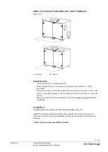
HERU 400 and 600 T/S
are supplied in one part.
HERU 800 and 1200 T/S
are supplied in two parts. Screw the unit together using the
fixed internal corner joints (rear) and the posts’ corner angles (front). Use the duct
connection to access the corner at the far end.
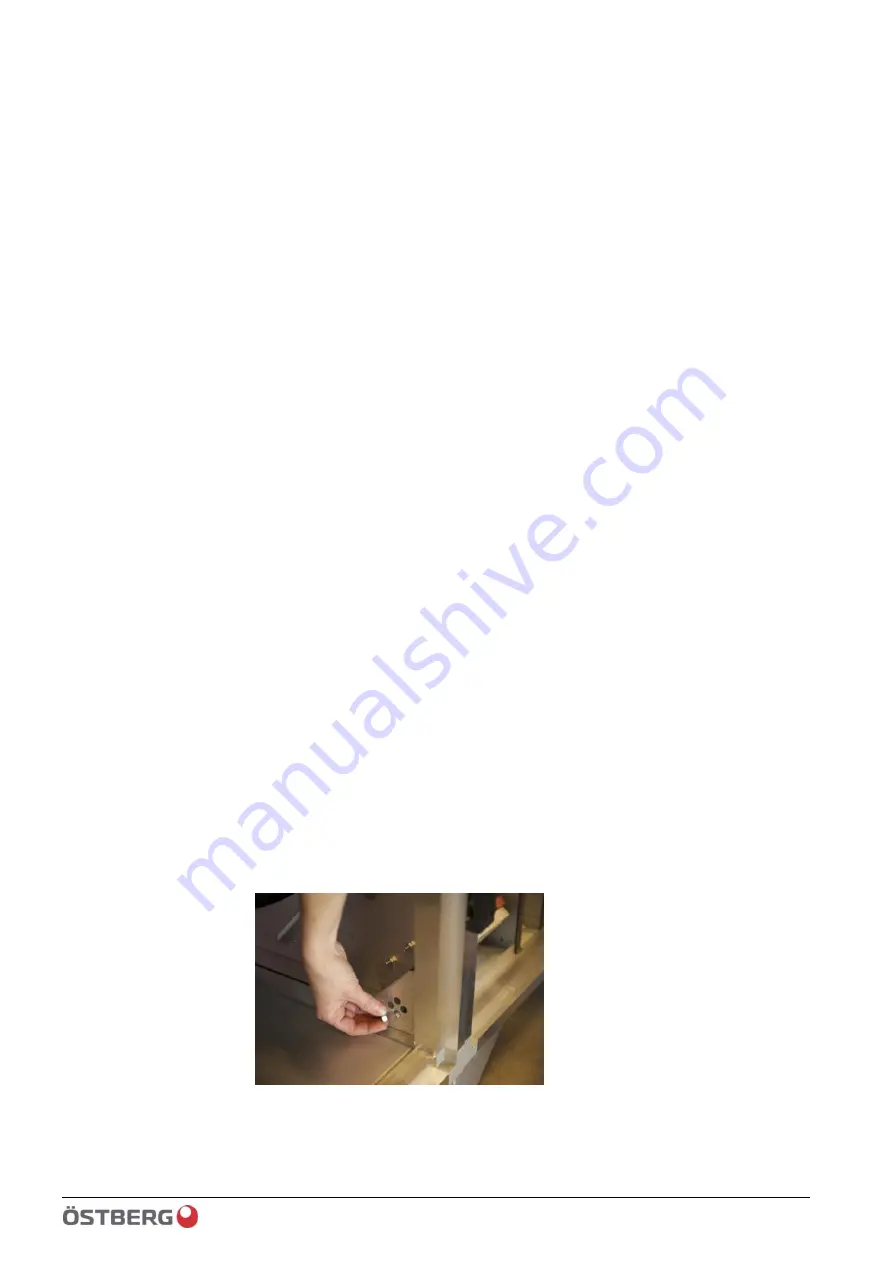
HERU 1600 and 2400 T/S
are supplied in three parts. In the rear corner, use the
threaded rod to pull the pieces together and tighten using the supplied nut.
Summary of Contents for HERU 400-2400 S
Page 1: ...U S E R M A N U A L E N H E R U 4 0 0 2 4 0 0 T S HERU T HERU S...
Page 2: ......
Page 14: ...14 120 Climatix HERU 400 2400 2018 02 13 Scope of assembly installation instructions...
Page 45: ...45 120 2018 02 13 Climatix HERU 400 2400 External components basic unit...
Page 97: ...97 120 2018 02 13 Climatix HERU 400 2400 Miscellaneous Menu structure Menu overview...
Page 98: ...98 120 Climatix HERU 400 2400 2018 02 13 Miscellaneous Start page Main index Unit...
Page 104: ...104 120 Climatix HERU 400 2400 2018 02 13 SERVICE HERU...
Page 111: ...111 120 2018 02 13 Climatix HERU 400 2400 SERVICE HERU...
Page 118: ...118 120 2017 11 03 Climatix HERU 400 2400 Troubleshooting...
Page 119: ......
Page 120: ......


