17 / 120
2018-02-13
Climatix HERU® 400-2400
Flowchart and function descriptions
3.
Flowchart and function descriptions
The flowchart and function descriptions describe most of the functions the controller can
handle. With regards to unit configuration, all functions may not be available in the
supplied model. Some can be selected in the HMI and are then described as Optional in
the HMI. Other functions do not have the external components required for selection. If
you have any questions about a specific function, please contact your nearest H. Östberg
AB sales office for assistance. The controller supplier constantly works with product
development and we reserve the right to continuously improve our product. As such,
there may be new functions in the software version this unit is equipped with, even if this
function is not described in the function description.
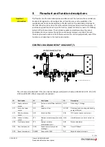
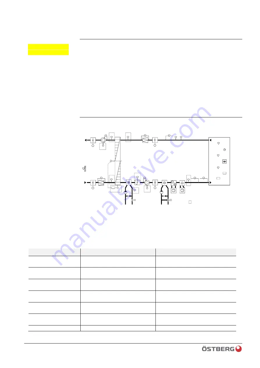
CONTROL DIAGRAM HERU® 400
-
2400 T/S
GT3
EMS-RV
GT1
GT42
GT2
FF-EC
EMS-M
TF-EC
RU1
TU1
ÖSTBERG HERU®CX
GP5
-
+
GTR
TM1
GN1
Cooling
water
CP2
SV2
GP3
SV1
CP1
GT8
Heating
Water
ELB
GT9
GTU
GF2
GQ1
GM1
GM1
GQ1
DX-C
DX-CHP
GP2
-
+
GP1
-
+
GP4
-
+
-
+
GF1
EMS
ST1
ST2
ST2
ST1
= included in standard HERU® CX
The unit comes standard with: Filter, fans, heat exchanger, water/electric heater, EMS, EMS RV, GT1, GT2, GT3,
GT42 and GT8/GT9. Other components are optional.
ID
Description
ID
Description
ID
Description
GT1
Supply air temp.
sensor
GP5
(Pressure switch/flow detector)
ELB
DX-C
DX-cooling
1…3
stage
GT2
Extract air temp.
sensor
GF1
Supply air flow
DX-CHP
Direct expansion cooling and heating
pump (or Water)
GT3
Outside air temp.
sensor
GF2
Extract air flow
GQ1
CO2 sensor, room or extract air
GT42 Exhaust air temp.
sensor
ST1
Damper actuator supply/outside
air
GM1
Humidity sensor, room or extract air
GT8
Frost temp. sensor
ST2
Damper actuator
extract/exhaust air
GN1
Presence detector
GT9
Over-temp sensor
EMS
Speed control rotary heat
exchanger
TM1
Timer OT/Boost
GTR
Room temp sensor
EMS-M
Drive motor EMS
TU1
Setpoint impact room pot.
Important
information
Summary of Contents for HERU 400-2400 S
Page 1: ...U S E R M A N U A L E N H E R U 4 0 0 2 4 0 0 T S HERU T HERU S...
Page 2: ......
Page 14: ...14 120 Climatix HERU 400 2400 2018 02 13 Scope of assembly installation instructions...
Page 45: ...45 120 2018 02 13 Climatix HERU 400 2400 External components basic unit...
Page 97: ...97 120 2018 02 13 Climatix HERU 400 2400 Miscellaneous Menu structure Menu overview...
Page 98: ...98 120 Climatix HERU 400 2400 2018 02 13 Miscellaneous Start page Main index Unit...
Page 104: ...104 120 Climatix HERU 400 2400 2018 02 13 SERVICE HERU...
Page 111: ...111 120 2018 02 13 Climatix HERU 400 2400 SERVICE HERU...
Page 118: ...118 120 2017 11 03 Climatix HERU 400 2400 Troubleshooting...
Page 119: ......
Page 120: ......

