


42 / 120
Climatix HERU® 400-2400
2018-02-13
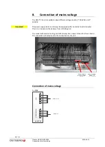
External components basic unit
9.
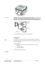
External components basic unit
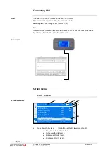
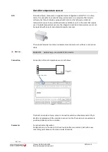
General
External sensors, actuators, etc. are connected to the HERU® CX unit or to an
expansion model, supplied separately (see chap. 11.) Terminal numbers are grouped as
follows:
Terminal
no.
Cable’s
max mm²
Group’s
placing
Voltage
1-10
4 mm²
HERU® CX
≤230
VAC
11-20
4 mm²
EXP1
≤230
VAC
31-40
4 mm²
HERU® CX
≤230
VAC
41-63
1 mm²
HERU® CX
≤
50 V
71-93
1 mm²
EXP1
≤
50 V
94-96
1 mm²
HERU® CX
Modbus RTU - RS485
97-100
1 mm²
HERU® CX & EXP1
≤
50 V/KNX
(internal communication)
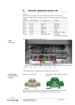
The following example shows a HERU® T CX:
1...10
31...40
41...55
56...63
94...100
GND
Plint nr.:
1...10
31...40
41...55
56...63
94...100
GND
Terminal
no.:
All terminals, except the feeding power connections, are type 2-level.
Beige connection terminal
Earth terminal (Green-yellow) connection
terminal
External side on the bottom level is connected with the bottom
level’s
internal side.
External side on the top level is connected to the internal
side’s
top level.
Layout
connection
Principle image
2-level connection
terminals
Summary of Contents for HERU 400-2400 S
Page 1: ...U S E R M A N U A L E N H E R U 4 0 0 2 4 0 0 T S HERU T HERU S...
Page 2: ......
Page 14: ...14 120 Climatix HERU 400 2400 2018 02 13 Scope of assembly installation instructions...
Page 45: ...45 120 2018 02 13 Climatix HERU 400 2400 External components basic unit...
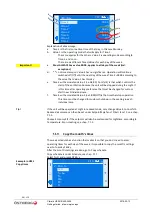
Page 97: ...97 120 2018 02 13 Climatix HERU 400 2400 Miscellaneous Menu structure Menu overview...
Page 98: ...98 120 Climatix HERU 400 2400 2018 02 13 Miscellaneous Start page Main index Unit...
Page 104: ...104 120 Climatix HERU 400 2400 2018 02 13 SERVICE HERU...
Page 111: ...111 120 2018 02 13 Climatix HERU 400 2400 SERVICE HERU...
Page 118: ...118 120 2017 11 03 Climatix HERU 400 2400 Troubleshooting...
Page 119: ......
Page 120: ......


