background image

B

edi

enungs

an

le

itung E

U

 8

0

ÖS
T

L

IN

G M

ar

kie

rs

ys

te

m

e

7

8.

0 El

ect
ro

ly

te

s

Ty

pe of

 m

ar

kin

g

C

ur

re

nt

V

olt

age

Fel
t

M

at

er

ial

E

lec

trol

yte

R

em
ar

ks

B

la

ck m

ar

kin

g

A

C

8 V

B

la

ck w

ith

co

nd

uc

tiv

e ne
t

S

tai

nles

s s

teel

6744,

 70 ,

72 ,

S

P

1

S

teel

676,

 74 ,

67/
10/
3,

 676R

74

C

hr

om

e ,

 N

icke
l

75

Zi

nk

 c

oat
ed

639

Tu

ng

sten

 C

ar

bid

e

332/

2

W

hit

e m

ar

kin

g

A

C

8 V

B

la

ck

 w

ith

co

nc

uc

tiv

e ne
t

B

lac

k ox

id

ized

(H

om
p s
team

ed)

114 S

of

t

N

eu

tra

liz

e w
ith

 N

8

119 M

edi
um

117 S

tro

ng

E

lect
ro

ly

te

 mu

st

 b

e d

iscard

ed

 af
te

r t

h

e marki

n

g

 p

ro

cess i

s co
mp
le

Summary of Contents for EU 80

Page 1: ...TREND MARKING SYSTEMS PO BOX 1311 CASTLE HILL NSW 2154 TEL 02 9629 9535 FAX 02 9629 7535 EMAIL trend trendmarking com au INTERNET www trendmarking com au Operating instructions EU 80 ...

Page 2: ...n manual and maintainence instructions must be carefully studied by all operating personnel before the system is used Copyrights All parts of this technical document including any patents described or trademarks contained therein are sole property of Ostling Markiersysteme GmbH Solingen Germany Without our prior approval no part of this document may be duplicated or made available to a third party...

Page 3: ...trols 3 3 0 Programming procedure 4 3 1 Preparing the marking head 4 3 2 Moistening the felt with electrolyte 4 3 3 stencils 5 4 0 Marking process 5 5 0 Maintainence 5 6 0 Accessories 5 7 0 Troubleshooting 6 7 1 Problem No mark 6 7 2 Problem Mark is unclear 6 7 3 Problem Black spots around the mark 6 8 0 Electrolytes 7 ...

Page 4: ...0 V AC the output voltage can be set to 8 V 16 V or 24 V AC or installed with 100 VA power 2 0 Technical Data 2 1 Controls Pos 1 Voltage 8 V AC Pos 2 Voltage 16 V AC Pos 3 Voltage 24 V AC Pos 4 Unit off Pos 5a Connection Positive cable Pos 5b Connection Negative cable Pos 6 ON OFF Switch Pos 7 Circuit breaker T 2 A Pos 8 Power cord Input voltage 230 V AC Output voltage 8 V 16 V oder 24 V AC Power ...

Page 5: ...e size as the surface of the marking head Fit a piece of conductive net Pos D so that the net covers the edge of the marking head Pos B approyimately 15 mm Now place the felt Pos C on the marking head and place the conductive net over the felt in order that you may fasten the cassette felt Pos E with the net Slip an o ring over the net and around the marking head so that everything is secure Pos A...

Page 6: ...check the felt and the conductive net Under normal use the felt will begin to collect carbon For this reason replace the felt as needed 5 0 Maintainence Regular maintainence of th marking machine is not necessary If you do experience difficulty however please turn to our service department Unauthorized opening of the machine will void the warranty 6 0 Accessories In order to make a more efficient ...

Page 7: ...at the surface to the product is clean Clean off excess dirt or oil with a dry cloth before you begin marking 7 3 Problem Black marks around the mark The stencil has not been handled properly It has been nicked and has a hole or is torn in some other way In order to correct the problem the best solution is to replace the stencil In an emergency you may cover the holes with adhesive tape until anot...

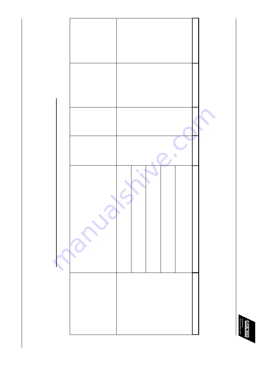
Page 8: ...rking AC 8 V Black with conductive net Stainless steel 6744 70 72 SP1 Steel 676 74 67 10 3 676R74 Chrome Nickel 75 Zink coated 639 Tungsten Carbide 332 2 White marking AC 8 V Black with concuctive net Black oxidized Homp steamed 114 Soft Neutralize with N8 119 Medium 117 Strong Electrolyte must be discarded after the marking process is comple ...

Page 9: ...ÖSTLING Markiersysteme ...

Reviews: