―E12―
6. CONNECTION PROCEDURE (continued)
6.1 Connection to the Welding Power Source and to the Gas regulator
NOTE:
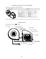
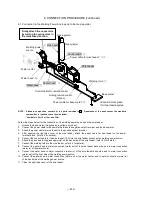
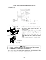
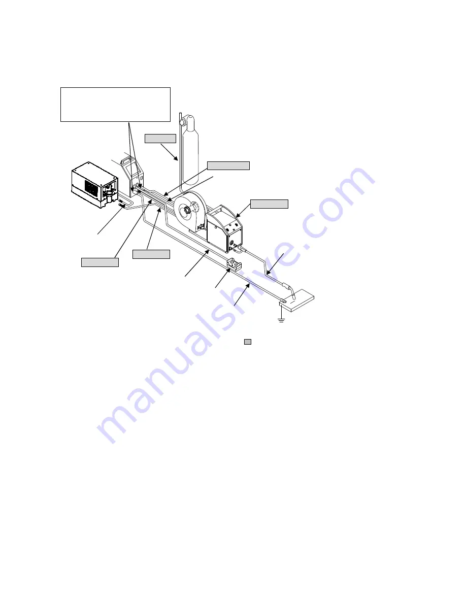
Standard composition consists of the parts indicated in
. Preparation of the parts except the standard
composition is required to use the wire feeder.
*Available in 5m, 10m, 15m, and 20m.
Follow the steps below for the connection of the welding power source and the wire feeder.
1. Ground the base metal (if required by local laws or codes).
2. Connect the power cable for base metal between the negative output terminal and the base metal.
3. Attach the power cable for wire feeder to the positive output terminal.
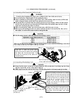
4. After opening the right-side cover of the wire feeder, attach the power cable for wire feeder to the power
terminal block. (refer 6.2 for details)
5. Connect the control cable for the wire feeder (10P) into the wire feeder socket on the welding power source.
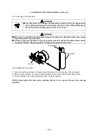
6. Attach the gas hose to the gas supply inlet on the back side of the wire feeder. (refer 6.4 for details)
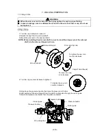
7. Connect the welding torch to the wire feeder. (refer 6.3 for details)
8. Connect the water hose to water connection (water out) of the wire feeder back side, and to water connection
(water in) of the water cooler.
9. Connect the water hose to water connection (water in) of the wire feeder back side, and to water connection
(water out) of the front side of the welding power source.
10. Connect the water hose to water connection (water out) of the water cooler, and to water connection (water in)
of the back side of the welding power source.
11. Close the right-side cover of the wire feeder.
Firmly attach the connectors
by turning the connectors in
the clockwise direction.
Water hose*
⑨
Water hose*
⑧
⑥
Gas hose*
Gas cylinder
Gas regulator
Control cable*
⑤
Wire feeder
Power cable for wire feeder*
③④
Power cable for base metal*
②
Control cable for remote control
Analog remote control
(Option)
Welding power
source
Ground a work piece
if a local law requires.
Water cooler
Water hose*
⑩
Base metal
Welding torch
⑦


