PRODUCT OVERVIEW
3
OI-6000K-X-X-X-NXP-X OPS_GUIDE_REV 1.0
1.3
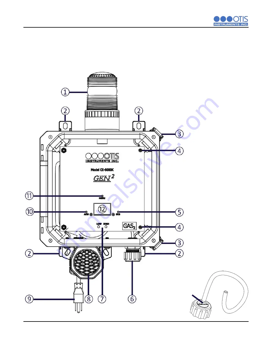
SYSTEM DIAGRAMS
Refer to the following diagrams for identification of the external and internal system components that may
be referred to in this manual.
1.3.1
EXTERNAL SYSTEM DIAGRAM
1
Strobe Light
2
Mounting Foot (4X)
3
Enclosure Latch (2X)
4
Front Panel Thumb Screw
(2X)
5
SUB Button
6
Sensor Housing Assembly
7
LOW and HIGH LED
Indicators
8
Dual-Tone Horn
9
Optional AC Power Cord
10
ADD Button
11
MENU Button
12
LCD Display Screen
13
Calibration Adapter Kit
(Sold Separately)
⑬
Summary of Contents for OI-6000K NXP Series
Page 1: ......
Page 2: ......
Page 67: ...APPENDICES OI 6000K X X X NXP X OPS_GUIDE_REV 1 0 62 Notes ...


