background image

3.  After use, remove any salt spray or moisture accumulated on the front panel 

(use a damp cloth with a mild detergent solution).

4.  Remove any debris from the o-ring located on the inside of the cover (Fig. 2, 

#21).

5.  Rinse the transducer in fresh, clean water, and dry it before storage.

6.  Keep the hand-held microphone as dry as possible (if applicable).

7.  Keep the bulkhead connector free of debris and moisture.

8.  Lubricate the seals with Zip Slip silicone grease or equivalent.  If the seals 

show wear or damage, replace them instead.

4.3 

TROUbLESHOOTING

This section contains instructions for troubleshooting the DRS-100 Diver Recall 

System.  The information found in Section 2, Setup and Operation (p. 5), should 

be used to supplement the information in this section.

Refer to Table 1 for instructions for troubleshooting basic problems with your 

DRS-100.  If the problem you are experiencing is not mentioned in the table, or 

if you have tried the suggested solutions and the problem persists, contact Ocean 

Technology Systems (see contact information on p. 13) for technical support or 

arrangements to send in the unit for repair.

4.4 

REMOVAL OR REPLACEMENT OF PARTS

4.4.1 

ELECTRONICS CHASSIS REMOVAL:

 To remove the electronics 

chassis from the housing, remove the ten panel screws.  Carefully pull the electron-

ics chassis straight out, taking care not to catch any wiring on the edge of the box 

or to place undue stress on the circuit board connectors or cables.

4.4.2 

bATTERY REPLACEMENT:

 If the battery pack fails and requires 

replacement, remove the battery container and replace the batteries (Section 3.2, 

p. 8).

4.4.3 

FUSE REPLACEMENT:

 If the fuse blows, replace it with a 6.0-amp, 

type MDL-6 slow-blow fuse. This fuse is located on the internal board.

11

TAbLE 1: Troubleshooting

Symptom


Probable Cause


Remedy

 No power to unit 

 Batteries exhausted 

Recharge batteries.

                                                   Failure of external DC             Check DC power source                                                                                          

                                                   power supply                            and connection.

Summary of Contents for DRS-100 Mod B

Page 1: ...Undersea Systems International Inc dba OCEAN TECHNOLOGY SYSTEMS Technology in Depth Diver Recall System DRS 100 Mod B User s ManuaL...

Page 2: ...zards of diving NOTE This manual and the information contained herein are provided for use as a mainte nance and operation guide No license or rights to manufacture reproduce and or sell either the ma...

Page 3: ...attery Charging Procedure 7 3 2 Battery Removal Replacement 8 Section 4 Maintenance and Troubleshooting 10 4 1 General 10 4 2 Preventive Maintenance 10 4 2 1 Check Prior to Every Dive 10 4 2 2 Mainten...

Page 4: ...er transducer The typical range is 500 meters but depends on the biological ambient noise level Divers within range listen using only their ears no electronic equipment is necessary The DRS 100 Diver...

Page 5: ...oximately 20 volts Battery type Two 12 volt 2 6 amp hour maintenance free re chargeable cells in series Battery life 5 hours at 20 duty cycle Recall Tone mode 3 hours nominal when using auxiliary inpu...

Page 6: ...ll illuminate when power is on 4 TONE RECALL This LED illuminates red when the continuous tone is utilized and green when the intermittent tone is activated 5 Panel ReliefValve Open this valve when ch...

Page 7: ...nel speaker is used to listen to any un derwater sounds within range e g biological or from human activity The hydrophone volume control 8 adjusts the listening volume 13 Handle You will find two hand...

Page 8: ...ducer receptacle on the panel and rotate the ring until a good connection is obtained 7 Strain relieve the transducer cable by securing a rope to the strain relief clip on the transducer Additionally...

Page 9: ...olume rotate the transmit volume control Fig 1 17 clockwise Release the PTT button when you have finished transmitting 2 2 2 3 External Audio To transmit audio from an external source connect an RCA p...

Page 10: ...reased to 20 volts Although the DRS 100 can operate with as little as 12 volts we recommend that you recharge the batteries Section 3 1 as soon as possible after the LED starts to illuminate If the ba...

Page 11: ...front panel 8 After a resting period of at least 15 minutes rotate the panel s relief valve clockwise to its closed position Note The RCS 30 smart charger cannot be used as an external power supply It...

Page 12: ...13 Reconnect J8 J10 J11 J12 and J13 to the circuit board assembly J10 J11 J12 and J13 are labeled and should be connected to the corresponding plugs on the circuit board P10 P11 etc J8 is probably not...

Page 13: ...nce and troubleshooting Alist of recommended spare parts appears in the Appendix at the end of the manual For service personnel or technically inclined users documentation for more advanced troublesho...

Page 14: ...are experiencing is not mentioned in the table or if you have tried the suggested solutions and the problem persists contact Ocean Technology Systems see contact information on p 13 for technical sup...

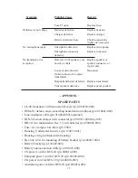
Page 15: ...ARTS LL 98 transducer with strain relief eyelet p n 900189 000 HSM 10 deluxe noise cancelling hand held microphone p n 910041 000 Line in adapter cable p n 914024 000 optional RCS 30 smart charger wit...

Page 16: ...reserve the right to decline responsibility where repairs have been made or attempted by other than an Ocean Technology Systems factory trained service center or properly trained personnel In no even...

Reviews: