background image

Oven CR-5000G* 


   page 2 

 
7. Controller setting: 

The  main  four-digit  display  on  the  electronic  temperature  controller  "K  48"  indicates 
permanently the real temperature in the oven. 


The controller has two levels of programming.  

 
Level 1 - working temperature setting: By pressing twice shortly the key P, the actual set 
value
  (  SP1  )  appears.  During  the  time  when  this  value  is  displayed,  the  value  can  be 
increased  or  decreased  by  pressing  the  keys  UP  or  DOWN.  Five  seconds  after  having 
released the keys,, the display returns back to its normal indication mode (the factory setting 
is at 175°C). 
 
Level 2 allows setting a number of parameters, which have been pre-set in the factory. Their 
codes appear when pressing the key P for more than 3 seconds. 
 
WARNING  !  –  It  is  recommended  not  to  modify  their  setting,  at  risk  to  make  the 
controller unusable! 
(In case of particular problems, ask for detailed Instructions). 
 
Left and right on the front  panel of the controller are  also   LEDs,  indicating the  ON or OFF 
position of the outputs (OUTPUT 1 only is used) and a shift index with 3 LEDs, working in 
the following way: 
 
  Red LED 

 flashing: Process value lower than 5 units of Set Point value 

  Red LED 

 ON: Process value lower within 5 units in respect of Set Point value Green 

  LED 

 ON: Process value equal to Set Point value 

  Red LED 

 ON: Process value upper within 5 units in respect of Set Point value 

  Red LED 

 flashing: Process value upper within 5 units of Set Point value 

 
Note :  When setting the working temperature, consider that it can be slightly different from 
that, indicated on the controller’s display. 
 
E.g. : the internal temperature inside 6 mm thick polypropyilene plates, obtained after at least 
20  minutes  of  stabilisation  (starting  from  the  having  moment  when  the  pre-selected  value 
has  been  reached)  is  about  5°  lower  than  displayed.   When  using  other  thicknesses  of 
material,  the  stabilisation  period  duration  and  the  temperature  lag  have  to  be  adjusted  in 
consequence.  
 
Uniformity over the working area: The temperature at the working level around 170° i s 
uniformly distributed within limits ±1° on an area,  limited to the distance of 100 mm from the 
side and back walls, but 150 mm from the door. 

Summary of Contents for PDQ Rollabout 5A

Page 1: ...la Hwy Chattanooga TN 37406 Fillauer Europe AB Kung Hans v 2 S 192 68 Sollentuna Model no 5001 1 50 5005 1 50 2100 50 2300 50 2305 50 2500 50 2600 50 2605 50 Hereby certifies that the Trautman carvers...

Page 2: ...ces de plastique par exemple pour la hanche Le four existe en 4 diff rentes tailles pour r pondre tous les besoins de thermoformage Chacun comporte un plateau r glable en hauteur assist hydrauliqueme...

Page 3: ...Rollabout Models 5A 6B 7C 8D 2 8E E n g l i s h M a n u a l CE c nOMcrrimon AI enuc WC3 crvilic Nonh Carolina 28787 800 2214769 828 658 8330 828 6 H 63F...

Page 4: ...tup 6 Oven Setup 7 Electrical Connections 8 Electrical Connections Over Temperature Shut Off Device Check 9 Electrical and Warning Labels 10 Oven Controls Operation 11 Operating Suggestions 12 208 240...

Page 5: ...s or gasses Be sure to allow sufficient ventilation around oven surfaces OTS Corp recommends 6 minimum Cleaning We recommend cleaning your PDQ Oven with either glass cleaner for water based stains or...

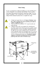
Page 6: ...ng the infrared emitters handle with care 2 The oven MUST be slid back 2 4 away from the cart before lifting 3 Lifting the side of the oven opposite the control panel insert the round section of the l...

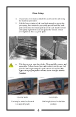
Page 7: ...Insert the bolt and lightly tighten the lock nut against the mount Do not over tighten as this is a pivot point 6 Flip the cart over onto the wheels Then carefully remove and unpack the Teflon sheete...

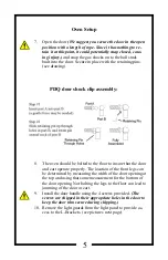
Page 8: ...to the floor to insure that the door and cart operate properly The location of the front legs can be determined by measuring the width of the door opening at the top and using that same measurement fo...

Page 9: ...t panel Holding the ceramic at the end of the emitter so as not to disconnect it from the glass portion of the emitter tighten the nuts at each end against the L Bracket Each emit ter and two L Bracke...

Page 10: ...s are provided with a 16A 6h plug and 8 of VDE rated cord The oven must be connected to an external circuit breaker and shut off mounted as close as possible to the oven 7 External Circuit Breaker and...

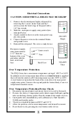
Page 11: ...n over temperature shut off device Limit Switch is supplied that will turn the emitters off if the temperature exceeds 500 F or 260 C A reset button is located on the back of the oven above the main p...

Page 12: ...gerous Electrical Voltage Caution refer to accompanying documents Caution Hot Surface Main Switch Control Oven Control Main Terminal Blocks 208 240 volt 1 phase 380 400 volt 3 phase 1 Amp Fuse 208 240...

Page 13: ...set point The MAIN SWITCH is located on the control panel on the front of the oven Rotate the knob to the ON position to enable oven use OFF ON 380 400 Volt Ovens The OVEN CONTROL SWITCH is located on...

Page 14: ...e lower position 2 Preheat the oven to the desired cooking temperature Normally between 375 F and 440 F or 190 C and 225 C 3 Select the appropriate size bubble forming frame and insert the plastic int...

Page 15: ...12 208 240V SINGLE PHASE CONTROllfR 12345678 ON OFF SWITCH l1MlT 5wrrCH FUSE 40WT LIGHT BULB INFRARED EMITTERS TRANSFORMER MERCURY CONTACTOR L1 L2 GND...

Page 16: ...13 2 1...

Page 17: ...h Selld prinrod insrruc rion l or lias bccn op r rcd undtr conditions n ro rhan or othe exc ling thosc Sc forlh in any spccifinrioos THIS WARRAYrY IS EXI RESSLY 1 LIEU OF ALL OTHER WARRA ITIES EXPRESS...

Page 18: ...Standards to which Conformity is Declared EN 61010 1 04 R2009 EN 61010 2 010 2003 EN 50081 1 1992 and EN 50082 1 1997 OTS Corporation 220 Merrimon Avenue Weaverville NC 28787 USA Industrial Infrared O...

Page 19: ...er having opened the top of the case remove the shelf The package containing the four feet and all corresponding screws deposited upon the oven The two counter weights are nailed against the side wall...

Page 20: ...position of the outputs OUTPUT 1 only is used and a shift index with 3 LEDs working in the following way Red LED flashing Process value lower than 5 units of Set Point value Red LED ON Process value l...

Page 21: ...steel shall be cleaned with a cloth soaked in the detergent solution and than wiped up with a dry cloth Personnel operating the units have to be well familiar with the present instructions In additio...

Page 22: ...trol phase is absent Check the 2 A fuse in the drawer and on the main panel Check the three 10A fuses and the main panel The electric circuit of one of the two heaters is interrupted disconnect the ov...

Page 23: ...rd GG J y 5x1 5 14 Spare parts On the sliding plate the following spare parts are deposited a 10 m roll of teflon coated fiber glass web one ElectronicTemp Controller K 48 one Heating element 750 W230...

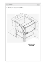
Page 24: ...Oven CR 5000G page 6 15 Dimensions of the oven on its feet OVEN CR 5000G 400V 4500W...

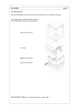
Page 25: ...nds and a stainless steel shelf For facilitating the assembling and mounting the shelf some details are given in exploded view Upper part of the foot The shelf Middle part of the foot Lower part of th...

Reviews: