background image

4  Introduction

The OTT ecoN is a measuring instrument for continuous determination of the

nitrate content of ground and surface water.
The following nitrate concentrations in water can be determined:

NO

3

-N

NO

3

NO

X

-N

1)

   (calibrated with standard NO

3

solution)

NO

X

1)

       (calibrated with standard NO

3

solution)

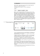
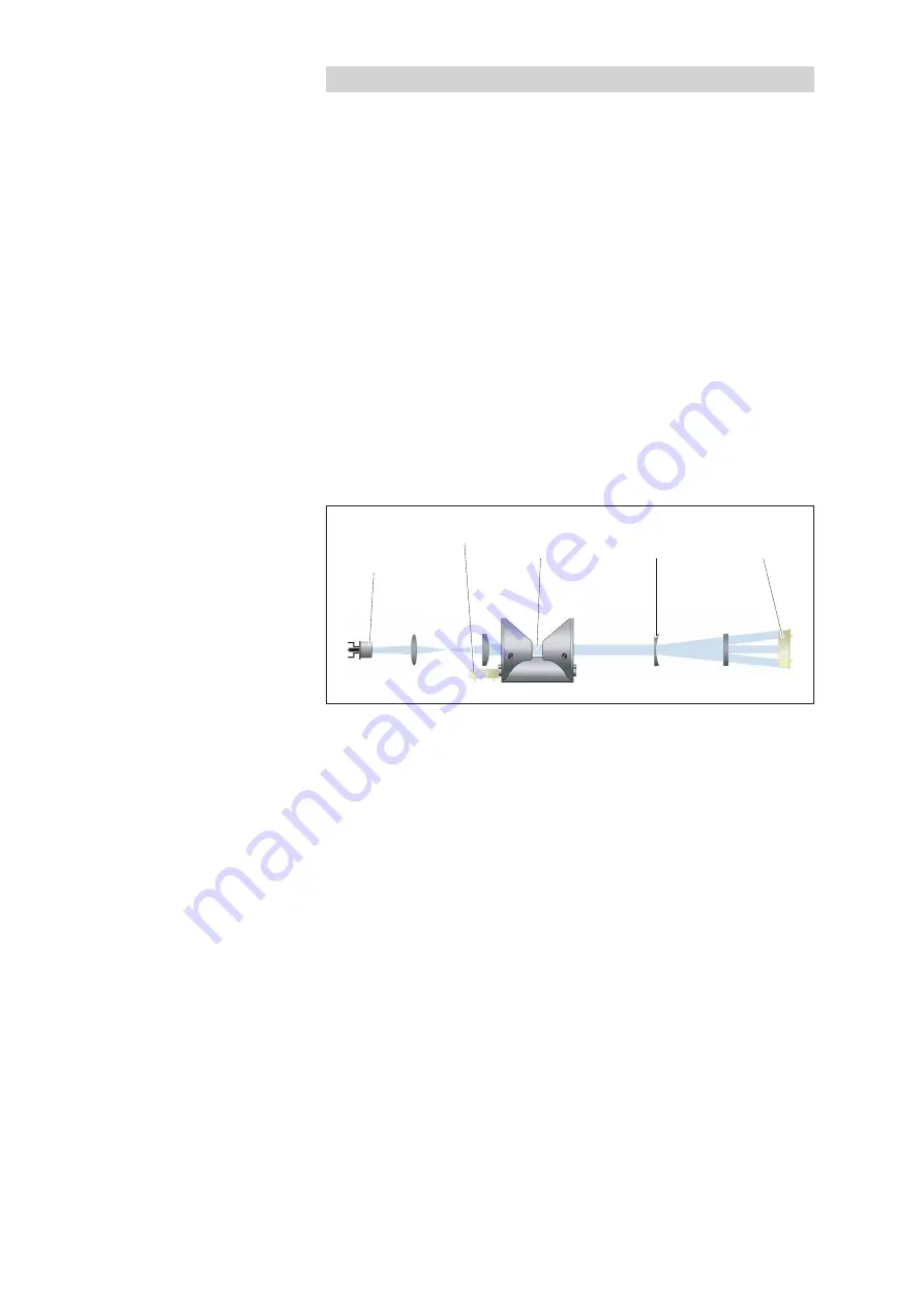
Figure 1 provides a schematic illustration of the measuring principle: A Xenon

flash lamp acts as a broad band light source. The light beam first passes through

an initial lens system, then passes through the measuring medium (water) in the

optical path, followed by a second lens system and is then received by three

detectors, which are photo diodes equipped with wavelength-specific filters. The

light beam at a wavelength of 212 nm is attenuated according to the nitrate con-

tent in the measuring medium. A reference diode before the optical path deter-

mines the unattenuated light output. This compensates for a fluctuating or deterio-

rating light source output. The additional attenuations measured at wavelengths of

254 nm and 360 nm also enable the OTT ecoN to compensate for organic inter-

ference or turbidity of the water.


To cover a nitrate measuring range of 0 to almost 900 mg/L with high precision

and resolution, the OTT ecoN is available with six different optical path lengths

(= measuring ranges; 0.3 - 10 mm).
The electrical connection to a data logger or a controller is via the permanently

installed connecting cable with M12 industrial connector. An RS-485 interface

with Modbus (RTU) transmission protocol is available for this purpose.
The nitrate sensor is equipped with an integrated web interface for setting the

operating parameters on the OTT ecoN. To use this, the OTT ecoN must be tem-

porarily connected to a PC using an interface box. Any internet browser can be

used as the user interface.
The measuring windows are equipped with anti-fouling technology with nano-coat-

ed glass keeping the windows largely free of dirt deposits. At problematic measur-

ing points with high organic interference, the nitrate sensor can also be fitted with a

mechanical wiper. The wiping movements can be set to any time interval (externally

controlled).

1)

Combined value for nitrate and nitrite, where both nitrate and nitrite are present in the water to be

measured. Differentiation between nitrate and nitrite is not possible with the OTT ecoN. The combined

values can be internally scaled using a factor if required.

Fig. 1: Optical measuring principle of the

OTT ecoN UV Nitrate Sensor.

Light source

(Xenon-

flash light)

Reference diode Optical

path

Optical 

lenses

Detectors

(3 x)

8

Summary of Contents for ecoN

Page 1: ...Operating instructions UV Nitrate Sensor OTT ecoN English...

Page 2: ...Technische nderungen vorbehalten...

Page 3: ...s 18 7 3 Write Single Registers function 0x06 19 7 4 Report Server ID function 0x11 19 8 Maintenance 20 8 1 Cleaning the OTT ecoN 20 8 2 Checking the OTT ecoN zero point 21 8 3 Calibrating the OTT eco...

Page 4: ...4...

Page 5: ...with M8 connector 10 metres Connecting cable with M8 socket and open ends 1 5 metres Extension cable for OTT ecoN M12 socket M12 connector 10 metres 63 300 018 9 0 25 metres 63 300 019 9 0 Extension...

Page 6: ...300 021 9 0 Operating instructions German 63 300 001 B D English 63 300 001 B E French 63 300 001 B F Spanish 63 300 001 B S Set of wiper blades 5 pcs including compatible wiper shaft mounting accesso...

Page 7: ...mbol placed next to them Note that the OTT ecoN may only be installed by a trained specialist e g electrician For further information see Chapter 5 Installing the OTT ecoN Ensure compliance with the e...

Page 8: ...L with high precision and resolution the OTT ecoN is available with six different optical path lengths measuring ranges 0 3 10 mm The electrical connection to a data logger or a controller is via the...

Page 9: ...cking and checking the reference values quality index can be carried out by support staff themselves The nitrate sensor can be calibrated either in the factory by the OTT repair centre or by trained s...

Page 10: ...optical path see Figure 3 the connecting cable may not be used for attaching or suspension it may not be subjected to any mechanical load in addition to its own weight contact between the sensor and...

Page 11: ...nless steel cable To do this attach the chain cable to the mounting rod with a shackle Suspend the connecting cable on the chain cable with an ISO anchor clamp or with cable ties Recommended minimum d...

Page 12: ...and the enclosed installation accessories see Accessories Attach the fastening clips as closely as possible to the ends of the sensors The substrate should be non corroding Attach the connecting cabl...

Page 13: ...ch the OTT ecoN to the float see Accessories as shown in Figure 6 Attach the fastening clamps as closely as possible to the ends of the sensors Secure the float against drifting with non corroding cha...

Page 14: ...ase note The M12 industrial connectors are not pressure water tight Not suitable for use under water degree of pro tection IP 67 Connect the red wire to the supply voltage 12 24 VDC Connect the blue w...

Page 15: ...Ethernet cable 1 G2 interface box 1 included with the G2 interface box Note When setting the operating parameters the voltage supply to the OTT ecoN comes from the G2 interface box Connect the M12 con...

Page 16: ...logger the sample storage interval is 30 seconds Clear clears and formats the internal memory Download copies the measured values recorded in the selected period Start date to End date to the PC Meas...

Page 17: ...the quality of a measurement 1 0 0 8 OK 0 8 0 5 Marginal 0 5 Error see Chapter 8 4 RefA Light intensity on the 212 nm channel this value should always be higher than 150 otherwise insufficient light r...

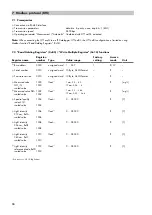
Page 18: ...lue range Factory setting Access mode Unit Bus address 0000 unsigned word 1 247 1 R W Serial number 0010 unsigned word 10 Byte ASCII Format R Firmware version 0015 unsigned word 10 Byte ASCII Format R...

Page 19: ...the register 0x0001 starts a single measure ment Afterwards the measured values can be read out via function Read Holding Registers 7 4 Report Server ID function 0x11 This function outputs the sensor...

Page 20: ...can lead to minor to moderately severe injuries particularly damage to Skin Dryness acetone degreasing effect skin changes skin damage chemical burns Eyes Cornea damage irritation chemical burns Respi...

Page 21: ...values occur Required accessories VALtub 10 or 50 mm length see Accessories Alternative to VALtub Suitable clean vessel in which the OTT ecoN can be placed in a slightly inclined position Ultra pure w...

Page 22: ...urement Call up the Measurement Parameter Mea sure now the OTT ecoN starts a measurement and displays the result in the browser window If the measured values are lower than 4 0 mg L NO3 N with 1 mm pa...

Page 23: ...The light intensity of the xenon flash lamp is too low ageing process Send the OTT ecoN to the OTT Hydromet GmbH repair centre RefD 13 000 and RefA RefB RefC 150 Take sensor out of water and perform...

Page 24: ...s of the European Union In accordance with the European Union guideline 2002 96 EC OTT takes back old devices within the member countries of the European Union and disposes of them in an appropriate w...

Page 25: ...ath 5 1 0 mg L NO3 N 2 mm optical path 5 0 5 mg L NO3 N 5 mm optical path 5 0 2 mg L NO3 N 10 mm optical path 5 0 1 mg L NO3 N Turbidity compensation Yes Data logger 2 GB T100 Response Time 20 s Measu...

Page 26: ...0 886 7 26 21 78 2 178 5 14 5 1 Nitrate NO3 N 0 60 0 5 1 5 0 15 5 1 Nitrate NO3 0 266 2 2 6 6 0 66 5 4 4 2 Nitrate NO3 N 0 30 0 25 0 75 0 075 5 0 5 Nitrate NO3 0 133 1 1 3 3 0 33 5 2 2 5 Nitrate NO3 N...

Page 27: ...Appendix A Dimensions all dimensions in mm 153 5 469 557 AF 20 48 3 28 27...

Page 28: ...h the optical path and remove any deposits on the measuring windows of the OTT ecoN The wiper blade then moves to a park position outside the optical path To start another wiping operation the supply...

Page 29: ...ding wiper shaft with associated wiper blade Installing the wiper shaft and wiper blade Lightly grease the O ring on the wiper shaft with the lubricating grease supplied Align the wiper shaft and inse...

Page 30: ...ft and attach it with the screws and Torx key supplied Align the wiper blade see figure and slide it onto the wiper shaft until it locks into place clicking sound Fig B4 Attaching the cover Wiper blad...

Page 31: ...ply the mechanical wiper with a constant voltage and start the wiping operation using a short trigger pulse Operating parameters for mechanical wiper Supply voltage 12 24 VDC Power consumption max 6 W...

Page 32: ...ndividual wires with wire end ferrules Connect the brown wire to the continuous supply voltage Connect the blue wire to earth Connect the white wire to a controller with trigger output Connect the bla...

Page 33: ...to be detached from the OTT ecoN Risk of damage to mechanical wiper gearing Avoid mechanical loads on the wiper shaft and the wiper blade Never turn the wiper shaft by hand At every fifth wiper blade...

Page 34: ...Operating temperature 2 40 C Storage temperature 10 70 C Actuation Connecting cable fixed connection 10 metres with 4 pin M8 connector connecting cable with M8 sock et and open ends 1 5 metres Trigger...

Page 35: ...Appendix C Note on Declaration of Conformity If necessary you can download the current version of the Declaration of Conformity for the OTT ecoN from our website as a PDF file www ott com resources 35...

Page 36: ...Document number 63 300 001 B E 01 0918 OTT Hydromet GmbH Ludwigstrasse 16 87437 Kempten Germany Telefon 49 831 5617 0 Telefax 49 831 5617 209 info ott com www ott com...

Reviews: