Service work
490E75=0_C
Ottobock | 111
4.16.2 Replacing a central leg support
CAUTION
Failure to observe installation instructions
Pinching, crushing due to falling parts
f
The central leg support and its individual parts have a substantial weight. Secure the parts against falling be-
fore loosening them.
f
Prerequisites:
If necessary: Move the seat tilt into a raised position.
Switch off the control device and deactivate the main fuse (see Page 15).
f
Tools: Allen wrench size 5, 6; open-ended or ring wrench size 13, 17; torque wrench with Allen insert size 5, 6
and socket size 13
Removing the central leg support
1) If necessary: Remove the seat plate (see Page 74 ff.).
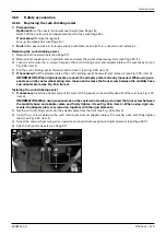
2) If necessary: Remove or open the cable attachments along the seat frame (see Fig. 237, item 1).
3) Loosen and remove the screws between the seat and central leg support on both sides (see Fig. 237/238,
item 2).
INFORMATION: Parts of the seat may be attached to these screws. Secure and fasten these parts again
immediately using the screws.
z@K@I?DIBJIOC@>JIuBPM<ODJIxOC@>@IOM<GG@BNPKKJMODN<OO<>C@?OJOC@>JH=DI<ODJI
N@<OC@DBCO<?EPNOH@IO<I?N@<OODGOHJ?PG@xN@<OAM<H@xJMN@<O=M<>F@ONN@@DB{¿ÀÄJM¿ÀÅ{
4) Remove the entire central leg support and safely set it aside (see Fig. 237/238, item 3).
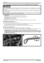
5) If necessary: Remove the individual leg supports from the centre insertion (see Fig. 239, item 1). To do so, loo-
sen and remove the 2 screws of the leg support (see Fig. 239, item 2).
6) If necessary: Remove the individual foot plates (see Fig. 240, item 1). To do so, loosen and remove the 4 screws
of the foot plate (see Fig. 240, item 2).
Installing the central leg support
1) If necessary: Attach the individual foot plates (see Fig. 240, item 1). To do so, insert the 4 screws of the foot
KG<O@<I?uMHGTODBCO@IOC@HOJ25 Nm (see Fig. 240, item 2).
2) If necessary: Attach the individual leg supports in the centre insertion (see Fig. 239, item 1). To do so, insert the
¿N>M@RNJAOC@G@BNPKKJMO<I?uMHGTODBCO@IOC@HOJ25 Nm (see Fig. 239, item 2).
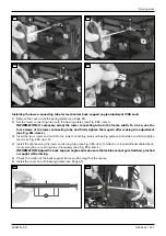
3) Loosen and remove the 2 screws with nut and washer on the central leg support (see Fig. 241, item 1).
4) Adapt the left and right holders of the central leg support to the width of the seat (see Fig. 241, item 2).
z@K@I?DIBJIOC@>JIuBPM<ODJIxOC@>@IOM<GG@BNPKKJMODN<OO<>C@?OJOC@>JH=DI<ODJI
seat height adjustment and seat tilt module, seat frame, or seat brackets. Reposition the left and right
holders symmetrically.
5) IN@MOOC@¿N>M@RNRDOCIPO<I?R<NC@MDIOJOC@NPDO<=G@M@>@NN@NDIOC@>@IOM<GG@BNPKKJMOx<I?uMHGTODBCO@I
them to 25 Nm (see Fig. 241, item 1).
6) Set the entire central leg support against the seat (see Fig. 237/238, item 3).
INFORMATION: Ensure that the wheels cannot collide with the leg supports.
7) IN@MOOC@¿N>M@RN=@OR@@IOC@N@<O<I?>@IOM<GG@BNPKKJMOJI=JOCND?@N<I?uMHGTODBCO@IOC@H{
INFORMATION: If you are attaching the central leg support to the seat brackets of a standard seat, tigh-
O@IOC@N>M@RNOJ¾½HN@@DB{¿ÀÅxDO@H¿{I<N@<OJM>JH=DI<ODJIN@<OC@DBCO<?EPNOH@IO
<I?N@<OODGOHJ?PG@xODBCO@IOC@N>M@RNOJ¿ÂHN@@DB{¿ÀÄxDO@H¿{
8) If necessary: Attach or close the loosened cable attachments along the seat frame (see Fig. 237, item 1).
9) Attach the seat plate (see Page 74 ff.).
10) ?EPNOOC@G@BNPKKJMON<>>JM?DIBOJOC@I@@?NJAOC@PN@M<I?>C@>FOC@HAJMuMHuO{
Summary of Contents for 490E75 Series
Page 1: ...490E75 0_C Service manual...
Page 38: ...Service work 490E75 0_C 38 Ottobock 57 58 59 60 61 62 63...
Page 41: ...Service work 490E75 0_C Ottobock 41 70 71 72 73 74 tt 75 76...
Page 55: ...Service work 490E75 0_C Ottobock 55 103 104 105 106 107 108 109 110...
Page 108: ...Service work 490E75 0_C 108 Ottobock 227 228 229 t 230 231 232...
Page 112: ...Service work 490E75 0_C 112 Ottobock 237 238 239 240 241...
Page 143: ...R Net wheelchair control 490E75 0_C Ottobock 143 Seat module pin assignment 287...
Page 161: ...490E75 0_C Ottobock 161...
Page 162: ...490E75 0_C 162 Ottobock...


