background image

Service work

490E75=0_C

Ottobock  |  125 

270


271

272


273

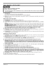
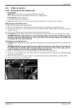
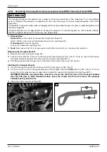
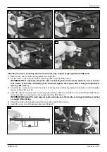
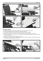
Mounting the supports

1)  GD?@OC@¾NONPKKJMOJIOJOC@>G<HKDIBKMJuG@JIOC@>JIOMJGK<I@GND?@’N@@uB{À½xG@AO“{

2)  @OOC@¿I?NPKKJMOJIOJOC@OP=@JIOC@NRDQ@GND?@’N@@uB{À½xMDBCO“{

3)  Provisionally set the depth of the tray top. Clamp  the swivel mechanism into place.

4)  Position the supports so they can be mounted at the front and with a safety distance on the outside.

5)  Mount the  supports  on  the  tray.  To  do  so,  drill  2 holes in the tray top with a diameter of 6.4 mm, respectively 

at the correct positions.

6)  Countersink the holes with a 90° spherical counter  sink.

7)  Attach each support with 2 of the supplied counter  sunk head screws. If necessary, compensate for the space 

between the supports and tray top with washers.

274


275


Summary of Contents for 490E75 Series

Page 1: ...490E75 0_C Service manual...

Page 2: ...17 4 6 2 Replacing the front cover 18 4 6 3 Replacing the rear cover 19 4 7 Batteries and power supply 20 4 7 1 Replacing the automatic circuit breaker 20 4 7 2 Replacing the batteries 21 4 7 3 Charg...

Page 3: ...eat height adjustment and seat tilt 81 4 13 8 Adjusting the centre of gravity VAS seat without module for combination of seat height adjustment and seat tilt 82 4 13 9 Replacing the seat frame with se...

Page 4: ...Installation 124 4 20 3 Adjusting the depth 126 5 Troubleshooting 127 5 1 Diagnostic steps 127 5 2 Display of errors faults R Net control unit 127 5 2 1 Graphical displays R Net control unit 127 5 2 2...

Page 5: ...ol parameters 153 7 4 5 Latched drive parameters 154 7 4 6 Seat parameters 155 8 Technical data 155 9 Appendixes 155 9 1 Approved seat brackets 155 9 2 Torque values of the screw connections 156 9 3 B...

Page 6: ...d not by the user of the device This service and maintenance manual refers to the respective spare parts catalogues and the instructions for use of the described products Please use these documents to...

Page 7: ...Back padding 11 Mobility base drive unit bracket 2 Back 12 Caster wheel 3 Seat module 13 Caster wheel splash guard 4 Side panel with armrest and clothing protector 14 Drive motor with brake release 5...

Page 8: ...Drive wheel splash guard 14 Leg support 6 Stabilising wheel swing arm 15 Seat cushion 7 Caster wheel splash guard 16 Control panel 8 Caster wheel 17 Side panel with arm support and clothing guard 9 D...

Page 9: ...ht of the wheelchair are permissible For further information please contact your national Ottobock team 2 3 Safety instructions for the use of tools and accessories CAUTION Use of unsuitable tools Pin...

Page 10: ...seat height before folding it up If this is not possible e g due to a defect in the seat height adjustment actuator then secure the seat during all work with the active support of a helper WARNING Unc...

Page 11: ...n performing any adjustment and installation work near installed cables ensure that the cables are suf ficiently long for all adjustment possibilities and cannot become pinched Use cable extensions an...

Page 12: ...e moved into the lowest position and the backrest folded down onto the seat The caster wheel is swivelled under the caster wheel swing arm The following accessories can be optionally dismantled or rem...

Page 13: ...our new configuration from the manu facturer see the overview of national Ottobock branches on the inside of the back cover 4 2 Instructions for adjustment WARNING Lack of stability against tipping Us...

Page 14: ...of a helper when the seat is folded up Always fold down the seat before jacking the wheelchair up or down NOTICE Incorrect lifting Damage to the product tearing off of side panels due to user error f...

Page 15: ...on the seat height adjustment actuator Actively secure the manually raised seat and the wheelchair against falling and tipping Perform the work only with the active support and assistance of a helper...

Page 16: ...oosening and the Allen wrench to further unscrew the support bolts 2 Pull out the locking bolt on the left side of the rear frame of the mobility base see Fig 8 item 2 and fold the seat back NOTICE Ri...

Page 17: ...and deactivate the main fuse see Page 15 If necessary Remove the legrests Removing the battery cover 1 Fold up the seat see Page 16 2 Push in the 2 mounting clips on the battery cover and lift the bat...

Page 18: ...the cables or the voltage converter due to improper removal of the cover Carefully lift off the front cover and disconnect the cables from the receptacles see Fig 13 item 1 5 Remove the front cover w...

Page 19: ...upper edge of the rear cover from the mounting clips on the frame and remove the rear cover panel see Fig 155 5 If necessary JK JPO OC M v OJMN RDOC HJPIODIB GDKN C AMJH OC M M JQ M N DB x DO H Instal...

Page 20: ...battery poles see Fig 17 item 1 4 INFORMATION Note the installed position of the battery cables and cable attachments Unscrew the battery cables of the automatic circuit breaker from the battery pole...

Page 21: ...see Page 17 3 Remove the insulator caps from the battery poles see Fig 19 item 1 4 INFORMATION Note the installed position of the batteries battery cables and cable attachments Unscrew all battery ca...

Page 22: ...the battery cables of the external charging receptacle from the battery poles see Fig 24 item 1 11 Loosen and remove the screw between the external charging receptacle and frame see Fig 255 12 Remove...

Page 23: ...fuse for lighting and external power supply f Prerequisites Optional Move the seat to the lowest seat height see Page 15 Switch off the control unit and deactivate the main fuse see Page 15 If necessa...

Page 24: ...egrests f Tools Allen wrench size 3 Removing the controller 1 Fold up the seat see Page 16 2 Remove the rear cover see Page 19 3 Fold down the seat see Page 16 4 Loosen and remove the 2 screws on the...

Page 25: ...with module carrier onto the back tube 3 IN MO OC N M RN OR I OC HJ PG MMD M I G HKN JI OC F OP I uMHGT ODBCO I OC H N DB x item 4 4 Connect the cables to the seat module according to their original i...

Page 26: ...Place the seat module with module carrier onto the upper connecting tube of the back 3 IN MO OC N M RN I IPON OR I OC N O HJ PG I PKK M JII ODIB OP I uMHGT ODBCO I OC H OJ 10 Nm see Fig 30 item 2 4 C...

Page 27: ...at the front and the cable points down not illustrated J Rear wheel drive RWD or mid wheel drive MWD Align the inclination sensor so that the cable outlet is at the rear and the cable points down see...

Page 28: ...he bus system see Fig 33 item 2 4 Connect the distributor relay to the back support angle adjustment actuator and the seat module see Fig 33 item 1 see Fig 36 z C C II G NNDBIH IO K I N JI OC M H DIDI...

Page 29: ...function Attach the ASM module underneath the seat plate see Fig 35 item 3 It is used for the seat tilt memory function Connect both distributor relays to the respective actuator and the seat module T...

Page 30: ...at height adjustment Leg sup port left Leg sup port right Distributor relay ISM memory function actuator Seat tilt Seat tilt with chin control Distributor relay ISM standard actuator Back sup port ang...

Page 31: ...t see Fig 38 Seat module for R Net control unit see Page 25 Input output module for R Net control unit see Fig 39 Inclination sensor see Fig 40 see Page 27 Removing the control module 1 INFORMATION No...

Page 32: ...ig 41 item 4 Loosen the set screw under the armrest and pull the swivel arm down and off see Fig 41 item 3 9 If necessary Remove the joystick module and LCD module see Page 33 Installing the TEN contr...

Page 33: ...32 6 Recalibrate the joystick Recalibrating the joystick 1 Switch the wheelchair control device off 2 Connect the programming dongle switch the wheelchair back on again and start on board programming...

Page 34: ...trol panel from the control panel rail 4 If necessary Remove and replace the control panel rail see Fig 46 item 3 z GG DINOMP ODJIN AJM OC JIOMJG K I G M DG M DI GP DI OC DINOMP ODJIN AJM PN PN M Inst...

Page 35: ...8 10 Replacing the manual centre tray control f Prerequisites Switch off the control device and deactivate the main fuse see Page 15 f Tools Phillips screwdriver size 3 Allen wrench size 3 4 open end...

Page 36: ...ert and hand tighten the 4 screws of the swivel mechanism see Fig 52 item 1 4 Insert and hand tighten the 2 screws of the charging receptacle see Fig 52 item 1 5 Install the control panel for the cent...

Page 37: ...ment see Fig 58 item 2 7 Remove the rear cover see Page 19 8 Connect the 24 V connection to the internal charging connection OBC of the controller see Fig 57 item 1 9 Connect the 24 V connection to th...

Page 38: ...Service work 490E75 0_C 38 Ottobock 57 58 59 60 61 62 63...

Page 39: ...module carrier and clamp see Fig 70 item 1 Also remove the clamp as you do so see Fig 70 item 2 5 Loosen and remove the two screws and nuts between the retaining plate and module carrier see Fig 71 it...

Page 40: ...le along the holder arm support holder and seat frame Secure the cable with the cable attach ments as you do so see Fig 69 item 1 INFORMATION Make sure that cables cannot get stretched pinched or caug...

Page 41: ...Service work 490E75 0_C Ottobock 41 70 71 72 73 74 tt 75 76...

Page 42: ...screws between the holder and tray see Fig 77 78 item 1 3 GD OC EJTNOD F DIOJ OC CJG M I uMHGT ODBCO I GG N M RN JA OC CJG M z A I NN MTx AJG OC CJG M JRI uMNO EPNO OC C DBCO JA OC EJTNOD F RDOC OC O...

Page 43: ...at or in the module carrier on the back support by default Disconnect the cable of the mo Vis controller from the cable extension not illustrated Remove the cable attach ments if necessary 2 Loosen an...

Page 44: ...RMATION On board programming is not activated on delivery of the control device In this case first carry out PC programming back up the parameters and activate on board programming when needed 3 G O O...

Page 45: ...wheel 1 G OC MDQ RC G JI OC MDQ v IB 2 IN MO OC N M RN DIOJ OC MDQ RC G I uMHGT ODBCO I OC H OJ 25 Nm in a crosswise sequence see Fig 82 item 1 82 4 9 2 Replacement tasks on the drive unit rear wheel...

Page 46: ...he drive wheel suspension 1 Remove the drive wheel see Page 45 2 CAUTION Pinching crushing blows due to loosened drive wheel swing arm Actively secure the drive wheel swing arm against falling Loosen...

Page 47: ...otors see Page 134 Page 141 ff f Prerequisites Optional Move the seat to the lowest seat height see Page 15 Switch off the control unit and deactivate the main fuse see Page 15 If necessary Remove the...

Page 48: ...ht motor item 2 left motor 5 Attach the controller see Page 24 6 Attach the rear cover see Page 19 7 Attach the drive wheel see Page 45 8 If the type of drive motors has been changed Reprogram the con...

Page 49: ...he drive wheel suspension between the drive wheel swing arm and drive unit bracket see Page 50 5 Install the drive motor with splash guard optional see Page 47 6 Attach the drive wheel see Page 45 90...

Page 50: ...ti tipper wheel 1 Position the anti tipper wheel with 1 adjusting washer on the anti tipper bracket 2 IN MO OC N M R I IPO DIOJ OC IOD ODKK M RC G I uMHGT ODBCO I DO N DB 95 4 9 2 7 Replacing the anti...

Page 51: ...MWD 4 9 3 1 Replacing the drive wheel splash guard f Prerequisites Optional Move the seat to the lowest seat height see Page 15 Switch off the control device and deactivate the main fuse see Page 15...

Page 52: ...acer sleeve between the suspension and the drive wheel swing arm see Fig 86 item 2 7 Loosen and remove the screw with 1 washer on the axle of the suspension see Fig 101 102 item 1 8 z JO OC DINO GG KJ...

Page 53: ...h off the control device and deactivate the main fuse see Page 15 If necessary remove the leg supports Jack up the wheelchair see Page 14 f Tools Allen wrench size 5 6 torque wrench with Allen insert...

Page 54: ...connection onto the drive wheel swing arm see Fig 111 item 2 INFORMATION The installed position of the spring connection depends on the installed drive motor N Page A I NN MTx M KG OC G AO I MDBCO NKM...

Page 55: ...Service work 490E75 0_C Ottobock 55 103 104 105 106 107 108 109 110...

Page 56: ...red release lever On the outside of the suspension see Fig 113 item 1 On the outside of the drive wheel swing arm see Fig 113 item 2 Spacer plates aligned to the inside see Fig 114 item 1 493T75 PK20...

Page 57: ...tread Replace the tyres if ne cessary f Prerequisites Optional Move the seat to the lowest seat height see Page 15 Switch off the control unit and deactivate the main fuse see Page 15 If necessary Re...

Page 58: ...Loosen and remove the 2 screws on the splash guard see Fig 121 item 1 INFORMATION A wheelchair with mid wheel drive MWD has caster wheels with a small splash guard CDN NKG NC BP M DN OO C RDOC JIGT N...

Page 59: ...er wheel swing arm To replace the bearing set see Page 60 6 Optional Remove the sleeves of the track stabiliser from the caster fork see Fig 124 item 3 see Page 62 7 Optional Remove the stopper of the...

Page 60: ...ring sleeve within the caster wheel swing arm Pull the bearing set 2 ball bearings and 1 bearing sleeve out of the caster wheel swing arm see Fig 125 item 1 z A OM F NO DGDN M JKODJI G DN DINO GG x NK...

Page 61: ...ORMATION Note the installed position of the Bowden cables and Bowden cable mountings Remove the caster wheel swivel lock with the Bowden cables Remove additional Bowden cable mountings and covers if n...

Page 62: ...llen insert size 4 Removing the track stabiliser 1 Remove the caster wheel see Page 57 2 Remove the caster fork with splash guard optional see Page 59 3 If necessary Remove the bearing set see Page 60...

Page 63: ...Incorrect dimensioning of the suspensions Damage to the suspensions and the product f The suspensions must be matched to the weight of the user and the total weight of the wheelchair Check whe ther th...

Page 64: ...NRDIB MH I uMHGT ODBCO I DO OJ 25 Nm see Fig 133 item 2 3 Insert the spacer sleeve into the drive unit bracket see Fig 133 item 1 and swivel the caster wheel swing arm upwards until the bearing eye of...

Page 65: ...heel swing arm 1 Loosen and remove the screw between the rigid element and caster wheel swing arm see Fig 134 2 Lower the caster wheel swing arm 3 Loosen and remove the 2 screws between the rigid elem...

Page 66: ...l swing arm see Page 61 4 Optional Remove the track stabiliser from the caster wheel swing arm see Page 62 5 Loosen the caster wheel swing arm from the suspension rigid element see Page 63 ff 6 JJN I...

Page 67: ...he drive wheel swing arm and caster wheel swing arm suspension see Fig 137 item 1 4 Carefully and slowly guide the caster wheel swing arm and drive wheel swing arm downwards 5 INFORMATION Note the ins...

Page 68: ...rew between the suspension and drive unit bracket with 1 washer see Fig 139 item 2 4 Lower the stabilising wheel swing arm and remove 1 spacer sleeve from the drive unit bracket see Fig 139 item 3 5 L...

Page 69: ...ext to the caster wheel swing arm axle see Fig 140 item 2 7 Carefully remove the plate from the Torsion Drive system see Fig 140 item 3 8 Reinstall the 2 screws with 1 washer each see Fig 141 item 1 9...

Page 70: ...alling the stabilising wheel swing arm 1 Slide the stabilising wheel swing arm onto the axle 2 IN MO OC N M R RDOC uSDIB R NC M JI OC SG I uMHGT ODBCO I DO OJ 15 Nm see Fig 142 item 2 3 Attach the sta...

Page 71: ...ers inner tube repair kit Removing the tyres 1 Remove the wheel see Page 45 Page 57 2 Optional for pneumatic tyres Let all the air out of the tyre 3 Loosen and remove the 5 screws on the inside of the...

Page 72: ...stem Suspension for caster wheel swing arm 140 140 front 150 rear 150 Spring stiffness of the suspensions Mobility base Overall weight of the wheelchair kg Front wheel drive FWD Rear wheel drive RWD D...

Page 73: ...es Switch off the control unit and deactivate the main fuse see Page 15 If necessary Remove the legrests Jack up the wheelchair see Page 14 Adjusting the springs RWD FWD see Fig 147 148 MWD see Fig 14...

Page 74: ...oving the seat plate VAS seat 1 Loosen and remove the 6 outer screws short on the seat plate see Fig 153 item 1 2 Loosen and remove the 2 inner screws long in the slotted holes of the seat plate see F...

Page 75: ...both connecting tubes on the back see Fig 156 item 1 5 Adjust the seat and back width as desired To do so slide the seat bars symmetrically in the adjustment tubes 6 IN MO OC N M RN I IPON DIOJ OC KKM...

Page 76: ...nstalled position of the seat height adapter The alignment of the seat height adapter depends on the size of the mobility base Loosen and remove the 2 screws on the seat height adapter see Fig 158 ite...

Page 77: ...installed on this screw connection Loosen and remove the screw with bushing seat bracket spacer optional and nut on both sides see Fig 161 item 2 8 Carefully pull the seat upwards off the mobility ba...

Page 78: ...act Ottobock Customer Service for more information Have the serial number of the power wheelchair ready It is used to determine the permissi ble positions f Prior to initial use test how changes in th...

Page 79: ...see item 2 7 Loosen and remove the screws between the seat frame and seat brackets on both sides see item 3 8 GD OC N O AM H OJ KJNDODJI OC O DN K MHDNND G AJM OC I R JIuBPM ODJI 9 IN MO OC N M RN OR...

Page 80: ...the mobility base Among other things the permissible centre of gravity depends on Type and size of the mobility base front wheel drive FWD see Fig 165 mid wheel drive MWD see Fig 166 rear wheel drive...

Page 81: ...can be adjusted by sliding the seat frame and combination seat height and seat tilt adjust ment module relative to the mobility base Among other things the permissible centre of gravity depends on Ty...

Page 82: ...leg supports f Tools Allen wrench size 6 open ended wrench size 13 torque wrench with Allen insert size 6 Dependencies The seat s centre of gravity can be adjusted by sliding the seat frame relative t...

Page 83: ...achments if necessary 8 If necessary Remove the seat brackets see Fig 167 item 2 To do so loosen and remove 2 screws each on all 4 seat brackets see Fig 177 item 3 Installing the seat frame and seat b...

Page 84: ...the cable attachments along the seat frame see Fig 178 item 1 6 Loosen and remove 2 screws on each of the 4 mounting points of the seat frame see Fig 179 item 1 7 Remove the seat frame Remove or open...

Page 85: ...n the eccentric of the seat height adjustment see Fig 183 item 1 9 WARNING Severe injuries due to pinching crushing if the seat falls down Secure the seat against fal ling down with the active support...

Page 86: ..._C 86 Ottobock 11 Fold up the seat see Page 16 12 IN MO OC N M RN OR I OC JOOJH JA OC AM H I OC N O C DBCO EPNOH IO OP OJM I uMHGT ODBCO I them see Fig 180 item 1 13 Fold down the seat see Page 16 180...

Page 87: ...he seat height adjustment sensor see Fig 182 item 2 8 Fold up the seat see Page 16 9 Loosen and remove the 2 screws between the bottom of the frame and the sensor bracket see Fig 186 item 1 10 INFORMA...

Page 88: ...must permit travel at full speed in this case 4 Switch off the control unit and deactivate the main fuse see Page 15 5 If the driving speed is reduced too soon too late or not at all readjust the sen...

Page 89: ...oller see Page 25 Page 19 3 Remove the retaining ring on the bolt of the seat tilt see Fig 189 item 1 4 CAUTION Injuries due to pinching crushing if the seat falls down Secure the seat against falling...

Page 90: ...t 1 Optional Remove the actuator for the power back angle adjustment see Page 94 2 Fold the back forwards onto the seat 3 Loosen and remove the bearing screw see Fig 191 192 item 1 4 Loosen and remove...

Page 91: ...unit and deactivate the main fuse see Page 15 Remove the seat cushion and back padding f Tools Allen wrench size 5 6 torque wrench with Allen insert size 5 6 Removing the bearing plate VAS seat 1 Remo...

Page 92: ...oving the back standard seat 1 Loosen and remove the screws in the bearing plates on both sides see Fig 191 192 item 2 2 Adjust the back 3 INFORMATION Note the installed position of the cables cable a...

Page 93: ...over on both bearing plates see Page 91 2 Loosen the 2 screws in the bearing plates on both sides see Fig 196 item 1 3 Adjust the back If necessary remove the cable attachments along the seat bars see...

Page 94: ...quisites Switch off the control unit and deactivate the main fuse see Page 15 f Tools Allen wrench size 4 torque wrench with Allen insert size 4 Removing the power back angle adjustment actuator stand...

Page 95: ...the manual back angle adjustment standard seat 1 Pull the release strap see Fig 200 item 1 and fold the back forwards onto the seat 2 Rotate the key ring on the release strap out of the eyelet of the...

Page 96: ...t of the upper connecting tube on both sides see Fig 202 item 2 6 Remove the upper connecting tube Remove the cable attachments if necessary see Fig 202 item 3 7 Loosen and remove the 2 screws and nut...

Page 97: ...bearing eye of the power back support angle adjustment actuator see Fig 205 item 1 5 INFORMATION Take note of the installed position of the actuator cable Remove the actuator for the power back angle...

Page 98: ...on both sides see Fig 202 item 1 5 Pull the inner tubes out of the upper connecting tube on both sides see Fig 202 item 2 6 Remove the upper connecting tube Remove the cable attachments if necessary...

Page 99: ...ack straps see Fig 209 210 item 1 2 Open and remove the Y hook and loop buckles on both ends of the back straps see Fig 211 3 Pull the free ends of the back straps out of the plastic clamps see Fig 20...

Page 100: ...ce work 490E75 0_C 100 Ottobock INFORMATION The two ends of the back straps should not overlap If necessary shorten the back NOM KN RDOCJPO CJJF I GJJK P FG N PIODG OC T I IJ GJIB M JQ MG K 209 210 21...

Page 101: ...he 2 clamping screws on the side panel holder see Fig 214 item 2 5 Pull the side panel holder out of the seat frame see Fig 214 item 3 Installing the side panel holder standard seat 1 Slide the side p...

Page 102: ...JQ OC N O KG O I DI M N OC N O RD OC PIODG OC N M R DN NND G N Page 4 Remove the side panel holder see Fig 215 item 4 Installing the side panel holder VAS seat 1 Set the side panel holder onto the sea...

Page 103: ...R NC M RDOC OC NO I M N O NH GG 5 Loosen and remove the arm support holder with the axle see Fig 218 item 1 6 Loosen and remove the rotation lock as well as the spacer washer and nut see Fig 219 item...

Page 104: ...position 9 Set the arm support holder and the axle onto the adaption see Fig 218 item 1 INFORMATION Position the axle so that the rotation lock securely engages in the recess Align the arm support hol...

Page 105: ...sion that deviates from the following tables or illustrations Seat depth cm Standard seat small see Fig 222 Standard seat large see Fig 223 Standard seat XL see Fig 224 38 A1 and G7 not allowed not al...

Page 106: ...th cm Standard seat small Standard seat large XL Front distance see Fig 225 item 1 Rear distance see Fig 213 item 2 Front distance see Fig 212 item 1 Rear distance see Fig 213 item 2 38 8 5 mm 5 0 mm...

Page 107: ...e elevating side panel VAS seat 1 Remove the standard side panel holder see Page 102 2 Remove the cover for the bearing plate see Page 91 3 INFORMATION Note the installed position of the screw connect...

Page 108: ...Service work 490E75 0_C 108 Ottobock 227 228 229 t 230 231 232...

Page 109: ...G M AMJH JQ I uMHGT ODBCO I OC OCPH N M R JI OC ND K I G holder see Fig 214 215 item 1 4 Optional Install the control panel with swivel arm see Page 32 233 4 15 6 Replacing the clothing protector f To...

Page 110: ...t bar as well see Fig 236 item 2 3 Optional Follow and disconnect the cable for the power legrest holder Remove or open additional cable attach ments if necessary 4 Pull the legrest holder out of the...

Page 111: ...so loosen and remove the 4 screws of the foot plate see Fig 240 item 2 Installing the central leg support 1 If necessary Attach the individual foot plates see Fig 240 item 1 To do so insert the 4 scre...

Page 112: ...Service work 490E75 0_C 112 Ottobock 237 238 239 240 241...

Page 113: ...en the cable attachments along the frame 9 If necessary Remove the light from the holder J Lighting front Pull the light off the magnet on the holder J Lighting rear Loosen the screw between the light...

Page 114: ...245 4 17 2 Replacing the fuse for the lighting The fuse for the lighting without StVZO is also the fuse for the external power supply optional To replace the fuse see Page 23 There is no replaceable...

Page 115: ...urb climbing assist backward and remove it see Fig 246 item 3 INFORMATION When rigid elements are used the adapter plate is already loosened When using sus pensions on the caster wheel swing arm loose...

Page 116: ...emove the legrests Jack up the wheelchair see Page 14 f Tools Allen wrench size 5 6 torque wrench with Allen insert size 5 6 socket wrench extension Removing the transport bracket 1 Remove the caster...

Page 117: ...cket 1 Remove the drive wheel see Page 45 2 Remove the drive wheel splash guard see Page 51 3 Loosen and remove the 2 screws on the transport bracket see Fig 249 item 1 To do so loosen and lower the s...

Page 118: ...5 Switch off the control device and deactivate the main fuse see Page 15 If necessary Remove the leg supports Jack up the wheelchair see Page 14 f Tools Allen wrench sizes 5 6 torque wrench with Allen...

Page 119: ...ove the drive wheel splash guard see Page 45 3 Remove the drive wheel suspension and carefully and slowly guide the loosened drive wheel swing arm down wards see Page 46 4 Fold up the seat see Page 16...

Page 120: ...sport eyelets with one sticker each see Fig 32 254 255 256 4 18 4 4 Installing the front transport eyelets transport kit for VAS seat f Prerequisites Switch off the control device and deactivate the m...

Page 121: ...T ODBCO I OC H B DI AO M H FDIB OC EPNOH IO N DB x DO H 3 IN MO OC ORJ N M RN I IPON DIOJ OC GJR M JII ODIB OP I MDIB KG O JI JOC ND N I uMHGT ODBCO I them see Fig 262 item 2 4 Install the cables alon...

Page 122: ...e the seat plate see Fig 264 see Page 74 2 Loosen and remove the screw with nut washer and bushing between the lap belt and seat frame see Fig 265 266 item 1 2 3 Remove the lap belt Installing the lap...

Page 123: ...ng the lap belt VAS seat 1 Loosen and remove the screw with bushing between the lap belt and seat frame on both sides see Fig 267 268 item 1 z C NGD GJ F M H DIN DI OC N O M RC I OC G K GO DN M KG N D...

Page 124: ...t Crushing or pinching due to adjustments which are too tight f Do not pinch the user when sliding in the product INFORMATION f The tray can only be ordered with a swing away control panel holder Swin...

Page 125: ...anism into place 4 Position the supports so they can be mounted at the front and with a safety distance on the outside 5 Mount the supports on the tray To do so drill 2 holes in the tray top with a di...

Page 126: ...IDNH I KPGG OC OM T AJMR M NGDBCOGT N uB x G AO 2 PGG OC KDI I NRDIB OC OM T R T OJ OC ND N uB x MDBCO 3 Seat the user in the seat 4 Fold the tray down and lock it with the pin 5 Adjust the depth CAUT...

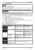
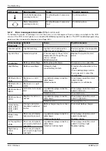
Page 127: ...oradic error message If applicable read and note down the error text displayed on the control panel Look up the potential cause in the error tables see Page 127 Page 130 ff and carry out the recommend...

Page 128: ...ve the wheelchair at low speed Check cabling plug contacts If error persists contact the manufacturer M1 Brake Error 1505 Brake error on left motor e g defective plug connection cable break Defective...

Page 129: ...cont roller too high e g defective plug connections Defective lamp Cool down phase Check plug connections and cable to light In case of recurrence replace light Memory Error Unspecified memory error...

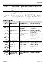
Page 130: ...on error on ad vanced stability module ASM Defective advanced stability module ASM Replace the advanced stability module ASM ASM Discon nected Advanced stability module ASM discon nected from controll...

Page 131: ...e connection to the battery charge the battery if the connection is good Left motor not connected e g defective plug connec tion cable break Check plug connections and cable to left motor Defective mo...

Page 132: ...to switch input Seat height adjust ment Seat in top position Seat functions active Defective seat height adjustment sensor Move seat to lowest position Check cabling plug contacts Replace and adjust...

Page 133: ...error Problem in the control unit Contact the manufacturer 5 4 Other errors not displayed This category includes errors that are not shown on the control panel or handheld programming device Reasons f...

Page 134: ...nment of the wiring the cable ends are marked with abbreviated designations of the components being connected The following designations apply among others f PM controller power module f LM light modu...

Page 135: ...harging connection OBC of the controller 279 1 Battery positive 2 Switch for drive away lock Inhibit 3 3 0 V Pin assignment on the charging receptacle of the control panel 280 1 Battery positive 2 Bat...

Page 136: ...otor see Page 47 7 Control panel see Page 32 3 Batteries see Page 21 8 Attendant control see Page 35 4 Light module see Page 30 9 Seat height adjustment actuator see Page 85 5 Lighting see Page 113 10...

Page 137: ...the handheld programming device 1 Switch the wheelchair control unit off 2 Optional for DTT handheld programming device Connect the connection cable for VR2 to the handheld programming device see Fig...

Page 138: ...period in which wheelchair is inactive before the control sys tem switches off If the time is set to 0 the system never switches off Joystick throw This allows programming so that full speed can be r...

Page 139: ...m turn deceleration Forward speed Single steps from 0 to 100 Setting of the minimum and maximum forward speeds of the wheelchair A high value enables a high speed The minimum value appears if the spee...

Page 140: ...s Minimum accele ration 1 increments of parameter Acceleration Setting of minimum forward and backward acceleration of the wheelchair This percentage acceleration value appears if the speed has been s...

Page 141: ...hours of operation of the wheelchair The timer starts running as soon as the joystick is deflected from the home position and stops running when the joystick returns to the home position The timer re...

Page 142: ...heelchair control 490E75 0_C 142 Ottobock Controller pin assignment 286 Looking at Bottom view of controller REBUS Connection Details PIN COLOUR LABEL 1 White CAN H 2 Blue CAN L 3 Red POWER H 4 Black...

Page 143: ...R Net wheelchair control 490E75 0_C Ottobock 143 Seat module pin assignment 287...

Page 144: ...t on the internal charging connection OBC of the controller 288 1 Battery positive 2 Switch for drive away lock Inhibit 3 3 0 V Pin assignment on the charging receptacle of the control panel 289 1 Bat...

Page 145: ...ustment actuator see Page 94 Page 96 3 Batteries see Page 21 9 Seat tilt actuator see Page 89 4 Control panel see Page 32 10 Seat height adjustment actuator see Page 85 5 LCD monitor Omni 11 Seat heig...

Page 146: ...ected to an unused bus slot 3 Switch on the control unit on the wheelchair and initialise it 4 M NN I CJG OC MJuG J POOJI PIODG OC JI J M KMJBM HHDIB NO MO N M I DN DNKG T For further information rega...

Page 147: ...erating modes A profile is a collection of programmable parameters which influence the operation and performance of the wheelchair There are typically 5 profiles each of which includes different drivi...

Page 148: ...er information on the parameters of special control is found in the 647G1242 instructions for use qualified personnel Special Controls R Net TEN Additional parameters which may be accessible with a di...

Page 149: ...be used following an analysis of all the associated risks i e no emer gency stop can be performed when driving or operating a variable motor in latched mode Ottobock shall not be liable for any losses...

Page 150: ...ate cannot be set higher than the maximum forward deceleration rate Maximum Rever se Acceleration Single steps from 0 to 100 Rate of acceleration of the wheelchair during reverse driving when the high...

Page 151: ...duced if the wheelchair becomes too jerky Tremor Damping Single steps from 0 to 100 This parameter can be used to reduce the impact of a user s hand tremor on joystick operation The higher the set val...

Page 152: ...can also be set interactively i e with the user moving the joy stick please see information following the table for details Joystick Dead band 10 to 50 in single steps Used to set the size of the neu...

Page 153: ...ection in Standby Yes no Used to set whether the joystick can be used to input various operating mo des while the system is in standby mode or whether standby mode is effec tively a sleep mode Standby...

Page 154: ...reased or decreased using short joystick movements Step reverse Step mode in both the forward and reverse direction Cruise Cruise mode in the forward direction only Joystick movement accelerates the w...

Page 155: ...ng range Description Acceleration 1 to 100 in sing le steps Acceleration rate for a specific ISM channel Deceleration 1 to 100 in sing le steps Deceleration rate for a specific ISM channel Up Speed 25...

Page 156: ...Recaro Size 1 38 50 cm 491C75 SS101 491C75 SS102 491C75 SS205 52 58 cm 491C75 SS111 491C75 SS112 491C75 SS205 Size 2 38 50 cm 491C75 SS111 491C75 SS102 491C75 SS205 52 58 cm 491C75 SS111 491C75 SS112...

Page 157: ...l 7 Programming tools Battery ies Drive unit s Actuator s Light s CAN CAN CAN PWM PWM DC DC Button Specialcontrol CAN CAN 4 Environmental control Analog 6 Smart device s Wireless Analog Digital Wirele...

Page 158: ...requested by the manufacturer in case of complaints f Provide the user or attendant with a copy of the completed record of delivery The user or attendant has been instructed in the use of the product...

Page 159: ...st Serial number Function setting depending on con figuration In good condition Damaged Exchange replace Whole product Visual inspection Seat folding mecha nism Covers Front cover Rear cover Battery c...

Page 160: ...ng arm Stabilising wheel swing arms Tyres Drive wheels Caster wheels Seat back Seat plate Seat frame Seat height adjust ment Seat tilt Back angle adjust ment Cushion upholstery Cables Belt system Cent...

Page 161: ...490E75 0_C Ottobock 161...

Page 162: ...490E75 0_C 162 Ottobock...

Page 163: ...OD JFPH JF MD DO ND GJF Jz D DT FlT NO I PG PMF T DIAJ JOOJ J F JH OM RRR JOOJ J F JH OM AMD OOJ J F GB_MD x MP C I PO G JJK_M ODQ G N DHJN N FG I FIJPI GB M GB_MD DIAJMH ODJI JOOJ J F AM RRR JOOJ J F...

Page 164: ...Ottobock 647G2002 en 06 2011 Otto Bock Mobility Solutions GmbH Lindenstra e 13 07426 K nigsee Germany www ottobock com Ihr Fachh ndler Your specialist dealer...

Reviews: