Troubleshooting
490E75=0_C
130 | Ottobock
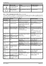
Error message;
Error code
Content
Cause
Possible measure
Switch Deta-
ched;
1E07
External on/off switch
disconnected from
control panel
e.g. defective cable connection
to control panel
Defective switch or control panel
Check cable connection and
switching function of the external
switch.
Replace control panel.
Switch Deta-
ched;
1E08
External profile/mode
switch disconnected
from control panel
Switch Short;
1E0D
Short circuit on external
on/off switch
Switch Short;
1E0C
Short circuit on external
profile/mode switch
Gone to Sleep
Control unit switches to
sleep mode
Extended inactivity while control
unit is switched on
Switch control unit off/on.
Charging
Battery charger is con-
nected
Battery charger is connected to
charging receptacle
Disconnect battery charger prior
to driving.
JS Static Time-
out
Joystick holding time
exceeded
Excessive joystick deflection
detected (control unit stops
drive system to prevent potential
damage to the motors)
Defective joystick
Switch control unit off/on.
Replace control panel/joystick.
Orientation Error Orientation error on ad-
vanced stability module
(ASM)
Defective advanced stability
module (ASM)
Replace the advanced stability
module (ASM).
ASM Discon-
nected
Advanced stability
module (ASM) discon-
nected from controller
e.g. defective plug connection,
cable break
Defective advanced stability
module (ASM)
Check cabling/plug contacts.
Replace the advanced stability
module (ASM).
Gyro Disconnec-
ted
Electronic track sta-
biliser (gyro module)
disconnected from
controller
e.g. defective cable connection
to controller
Defective gyro module
Replace gyro module.
Gyro Prf Active
Electronic track stabi-
liser (gyro module) is
activated
Electronic track stabiliser (gyro
module) is disrupted by the
movement of a different means of
transportation (e.g.train, ship) in
standby
Defective gyro module
To move the wheelchair, select
the "No Assist" driving profile for
safety reasons.
Replace gyro module.
5.3
Display of errors/faults (VR2 control unit)
5.3.1 Visual displays (VR2 control unit)
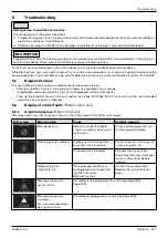
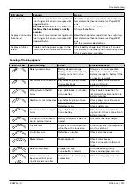
Error messages are displayed via the flashing signals of the "battery capacity" LED display on the control panel.
LED display
Meaning
Action
Fast flashing
The control system detects an error.
Interpret the flashing signals (see Page 131),
connect the handheld programming device,
determine the error code (see Page 132) and
take the recommended actions.
Summary of Contents for 490E75 Series
Page 1: ...490E75 0_C Service manual...
Page 38: ...Service work 490E75 0_C 38 Ottobock 57 58 59 60 61 62 63...
Page 41: ...Service work 490E75 0_C Ottobock 41 70 71 72 73 74 tt 75 76...
Page 55: ...Service work 490E75 0_C Ottobock 55 103 104 105 106 107 108 109 110...
Page 108: ...Service work 490E75 0_C 108 Ottobock 227 228 229 t 230 231 232...
Page 112: ...Service work 490E75 0_C 112 Ottobock 237 238 239 240 241...
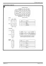
Page 143: ...R Net wheelchair control 490E75 0_C Ottobock 143 Seat module pin assignment 287...
Page 161: ...490E75 0_C Ottobock 161...
Page 162: ...490E75 0_C 162 Ottobock...

