R-Net wheelchair control
490E75=0_C
Ottobock | 141
Parameter
Setting range Description
Minimum turn
deceleration
1% increments
of parameter
"Turn decelera-
tion value"
Setting of the minimum turn deceleration of the wheelchair.
This percentage turn deceleration value appears if the speed has been set
to 1.
Programming example:
• Turn Deceleration = 80 and Minimum Turn Deceleration = 25%
• Turn Deceleration at step 1 = 25% of 80 = 20
• Speed settings 2, 3 and 4 will interpolate linearly between 20 and 80
• Turn deceleration at step 2 = 35
• Turn deceleration at step 3 = 50
• Turn deceleration at step 4 = 65
6.3.3 Log functions
The following functions are logged by the VR2 control and can be read with the corresponding hardware:
Function
Description
Memory functions
VR2 is equipped with a timer and troubleshooting report function. They can be read and
deleted with the help of the DTT or PC programming device.
Read timer
VR2 is equipped with a timer that records the hours of operation of the wheelchair. The timer
starts running as soon as the joystick is deflected from the home position and stops running
when the joystick returns to the home position. The timer records the number of hours for
which the wheelchair is in use.
Clear timer
This function resets the VR2 control's timer. This function can only be used with the PCPb
and PCPc versions of the PC programming device.
Read system log
VR2 is equipped with a troubleshooting report system which stores the number of occurren-
ces of the last 8 detected system problems. This allows you to view the contents.
Erase system log
With this function the troubleshooting report from the VR2 control can be deleted. This func-
tion can only be used with the PCPb and PCPc versions of the PC programming device.
7
R-Net wheelchair control
7.1
Installation and wiring
INFORMATION
For clear assignment of the wiring, the cable ends are marked with abbreviated designations of the components
being connected. The following designations apply among others:
f
PM = controller/power module
f
ISM = seat module
f
JSM = joystick module/control panel
f
Akt. = actuator
f
Inh. = switch
Summary of Contents for 490E75 Series
Page 1: ...490E75 0_C Service manual...
Page 38: ...Service work 490E75 0_C 38 Ottobock 57 58 59 60 61 62 63...
Page 41: ...Service work 490E75 0_C Ottobock 41 70 71 72 73 74 tt 75 76...
Page 55: ...Service work 490E75 0_C Ottobock 55 103 104 105 106 107 108 109 110...
Page 108: ...Service work 490E75 0_C 108 Ottobock 227 228 229 t 230 231 232...
Page 112: ...Service work 490E75 0_C 112 Ottobock 237 238 239 240 241...
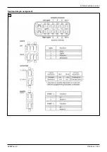
Page 143: ...R Net wheelchair control 490E75 0_C Ottobock 143 Seat module pin assignment 287...
Page 161: ...490E75 0_C Ottobock 161...
Page 162: ...490E75 0_C 162 Ottobock...

