Service work
490E75=0_C
20 | Ottobock
4.7
Batteries and power supply
CAUTION
Short circuit
Burns, injuries; damage to electrical/electronic components due to improper battery handling
f
Deactivate the main fuse before performing any work on the battery.
f
Only use insulated tools to perform maintenance work on the batteries.
f
Never connect the two poles of a battery with metal conductors or tools.
f
Ensure correct polarity when you connect the battery cables. Please refer to the battery circuit diagram on the
inside of the battery cover and on Page 156.
4.7.1 Replacing the automatic circuit breaker
f
Prerequisites:
Optional: Move the seat to the lowest seat height (see Page 15).
Switch off the control unit and deactivate the main fuse (see Page 15).
If necessary: Remove the legrests.
f
Tools: Allen wrench size 3; open-ended or ring wrench size 10; torque wrench with socket size 10
Removing the automatic circuit breaker
1) Fold up the seat (see Page 16).
2) Remove the battery cover (see Page 17).
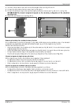
3) Remove the insulator caps from the battery poles (see Fig. 17, item 1).
4) INFORMATION: Note the installed position of the battery cables and cable attachments.
Unscrew the battery cables of the automatic circuit breaker from the battery poles (see Fig. 17, item 2).
5) Remove the cable attachments on the battery cables of the automatic circuit breaker (see Fig. 17, item 3).
6) Loosen and remove the 2 screws on the automatic circuit breaker (see Fig. 17, item 4).
7) Remove the automatic circuit breaker and 2 battery cables from the cover (see Fig. 18).
Installing the automatic circuit breaker
1) Route the 2 battery cables through the cover and insert the automatic circuit breaker into the cover panel (see
Fig. 188).
2) IN@MO<I?uMHGTODBCO@IOC@¿N>M@RNDIOC@<POJH<OD>>DM>PDO=M@<F@MN@@DB{¾ÄxDO@HÁ{
3) Connect the battery cables of the automatic circuit breaker to the battery poles according to their original ins-
talled position (see Fig. 17, item 2). Tighten the screws on the battery poles to 6 Nm.
4) Place the insulator caps onto the battery poles (see Fig. 17, item 1).
5) Lay the battery cables of the automatic circuit breaker along the other battery cables and secure them with cable
attachments (see Fig. 17, item 3).
6) Attach the battery cover (see Page 17).
7) Fold down the seat (see Page 16).
17
18
Summary of Contents for 490E75 Series
Page 1: ...490E75 0_C Service manual...
Page 38: ...Service work 490E75 0_C 38 Ottobock 57 58 59 60 61 62 63...
Page 41: ...Service work 490E75 0_C Ottobock 41 70 71 72 73 74 tt 75 76...
Page 55: ...Service work 490E75 0_C Ottobock 55 103 104 105 106 107 108 109 110...
Page 108: ...Service work 490E75 0_C 108 Ottobock 227 228 229 t 230 231 232...
Page 112: ...Service work 490E75 0_C 112 Ottobock 237 238 239 240 241...
Page 143: ...R Net wheelchair control 490E75 0_C Ottobock 143 Seat module pin assignment 287...
Page 161: ...490E75 0_C Ottobock 161...
Page 162: ...490E75 0_C 162 Ottobock...


