Service work
490E75=0_C
Ottobock | 21
4.7.2 Replacing the batteries
WARNING
Accumulation of explosive gases in the battery compartment due to use of incorrect batteries
Severe injuries due to explosion in battery compartment
f
Use only AGM or gel batteries which have been approved for this product by the manufacturer. Please contact
Ottobock regarding the purchase of replacement batteries.
NOTICE
Unauthorised battery replacement
Battery damage due to unauthorised changes to the product
f
Battery replacement may only be performed by qualified personnel trained by the manufacturer.
f
The charging profile of the battery charger established at the factory matches the batteries included in the
scope of delivery and may not be altered independently.
INFORMATION
If you want to install batteries with a M5 terminal, a washer must be used to compensate for the size difference
between the M5 terminal and the M6 cable lug.
f
Prerequisites:
Optional: Move the seat to the lowest seat height (see Page 15).
Switch off the control unit and deactivate the main fuse (see Page 15).
If necessary: Remove the legrests.
f
Tools: open-ended or ring wrench size 10
Removing the batteries
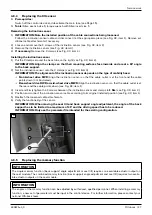
1) Fold up the seat (see Page 16).
2) Remove the battery cover (see Page 17).
3) Remove the insulator caps from the battery poles (see Fig. 19, item 1).
4) INFORMATION: Note the installed position of the batteries, battery cables and cable attachments.
Unscrew all battery cables from the battery poles (see Fig. 19, item 2).
5) If necessary: Remove the cable attachments on the battery cables (see Fig. 19, item 3).
6) If necessary: Carefully move transverse cables aside (see Fig. 19, item 4). Remove additional cable attachments
if necessary.
7) WARNING! Risk of tipping due to changed centre of gravity. Secure the seat and the wheelchair against
tipping and falling with the active support of a helper.
Lift the batteries up and out by the handles (see Fig. 20).
Installing the batteries
1) Use the handles to carefully set the batteries into the battery tray in the mobility base.
z@@NO<=GDNCOC@JMDBDI<Gx>MJNNRDN@KG<>@H@IOJAOC@=<OO@MTKJG@NN@@=<OO@MT>DM>PDO
diagram in the battery cover and on Page¾ÂÃ{
2) Connect all battery cables to the battery poles according to their original installed position (see Fig. 19
3) 9, item 2). Tighten the screws on the battery poles to 6 Nm.
4) Place the insulator caps onto the battery poles (see Fig. 19, item 1).
5) Fasten the cable attachments between the battery cables (see Fig. 19, item 3).
6) If necessary: Move transverse cables to their original installed position and secure with cable attachments if
necessary (see Fig. 19, item 4).
7) Attach the battery cover (see Page 17).
8) Fold down the seat (see Page 16).
Summary of Contents for 490E75 Series
Page 1: ...490E75 0_C Service manual...
Page 38: ...Service work 490E75 0_C 38 Ottobock 57 58 59 60 61 62 63...
Page 41: ...Service work 490E75 0_C Ottobock 41 70 71 72 73 74 tt 75 76...
Page 55: ...Service work 490E75 0_C Ottobock 55 103 104 105 106 107 108 109 110...
Page 108: ...Service work 490E75 0_C 108 Ottobock 227 228 229 t 230 231 232...
Page 112: ...Service work 490E75 0_C 112 Ottobock 237 238 239 240 241...
Page 143: ...R Net wheelchair control 490E75 0_C Ottobock 143 Seat module pin assignment 287...
Page 161: ...490E75 0_C Ottobock 161...
Page 162: ...490E75 0_C 162 Ottobock...


