Service work
490E75=0_C
32 | Ottobock
4.8.7 Replacing the TEN° control panel
INFORMATION
Recalibrate the joystick after replacing a module (see Page 33). Otherwise the directional stability of the
wheelchair may be affected, or it may not be possible to reach the maximum speed.
f
Prerequisites:
Switch off the control unit and deactivate the main fuse (see Page 15).
f
Tools: Phillips screwdriver size 3; Torx wrench size T10; Allen wrench size 3
Removing the TEN° control panel
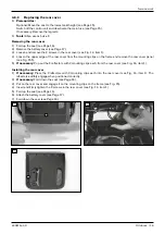
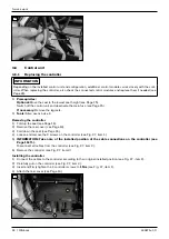
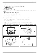
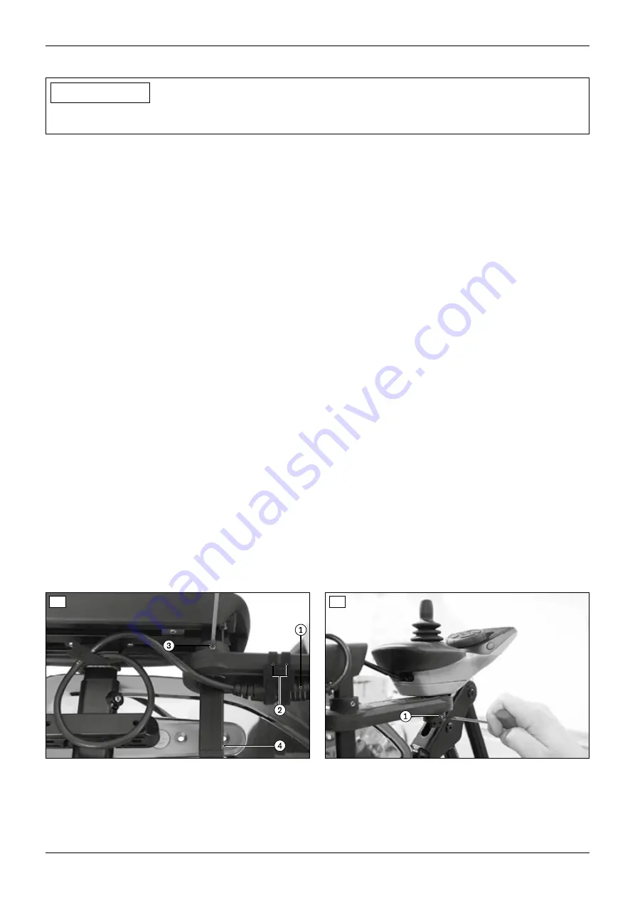
1) Disconnect the cable of the control panel from the cable extension (see Fig. 41, item 1). Remove the cable at-
tachments if necessary (see Fig. 41, item 2).
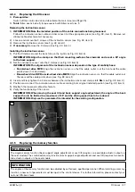
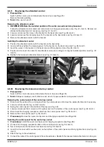
2) Loosen the 2 set screws on the swivel arm under the control panel (see Fig. 42, item 1).
3) Pull the control panel up and out of the swivel arm.
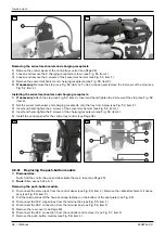
4) Loosen and remove the Torx screw in the cover under the control panel (see Fig. 43, item 1).
5) Remove the cover under the control panel (see Fig. 43, item 2).
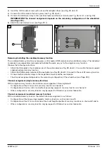
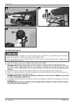
6) Loosen and remove the 2 screws on the bottom of the control panel (see Fig. 44, item 1).
7) Remove the retaining plate from the bottom of the control panel (see Fig. 44, item 2).
8) If necessary: Remove and replace the swivel arm. To do so, loosen and remove the retainer (see Fig. 41, item 4).
Loosen the set screw under the armrest and pull the swivel arm down and off (see Fig. 41, item 3).
9) If necessary: Remove the joystick module and LCD module (see Page 33).
Installing the TEN° control panel
1) If necessary: Install the joystick module and LCD module (see PagePage 33).
2) If necessary: OO<>COC@NRDQ@G<MH{JOCDN=TNGD?DIBOC@NRDQ@G<MHJIOJOC@<MHM@NOAMJH=@GJR<I?uMHGT
tightening the set screw under the armrest to 3 Nm (see Fig. 41, item 3).
3) Place the retaining plate on the bottom of the control panel (see Fig. 44, item 2).
INFORMATION: Align the retaining plate according to the control panel installation position: Fig. 44
shows the alignment of the retaining plate for installation on the right side of the wheelchair. For ins-
O<GG<ODJIJIOC@G@AOND?@JAOC@RC@@G>C<DMxMJO<O@OC@M@O<DIDIBKG<O@=T¾Å½Ü{
4) IN@MO<I?uMHGTODBCO@IOC@¿N>M@RNDIOC@M@O<DIDIBKG<O@<I?OC@=JOOJHJAOC@>JIOMJGK<I@GN@@DB{ÁÁx
item 1).
5) Place the cover on the bottom of the control panel (see Fig. 43, item 2).
6) IN@MO<I?uMHGTODBCO@IOC@JMSN>M@RDIOC@>JQ@MPI?@MOC@>JIOMJGK<I@GN@@DB{ÁÀxDO@H¾{
7) Insert the control panel into the swivel arm from above.
8) Firmly tighten the 2 set screws on the swivel arm under the control panel to 3 Nm (see Fig. 42, item 1).
9) Connect the cable of the control panel to the cable extension (see Fig. 41, item 1). Reattach the loosened cable
attachments when doing so (see Fig. 41, item 2).
41
42
Summary of Contents for 490E75 Series
Page 1: ...490E75 0_C Service manual...
Page 38: ...Service work 490E75 0_C 38 Ottobock 57 58 59 60 61 62 63...
Page 41: ...Service work 490E75 0_C Ottobock 41 70 71 72 73 74 tt 75 76...
Page 55: ...Service work 490E75 0_C Ottobock 55 103 104 105 106 107 108 109 110...
Page 108: ...Service work 490E75 0_C 108 Ottobock 227 228 229 t 230 231 232...
Page 112: ...Service work 490E75 0_C 112 Ottobock 237 238 239 240 241...
Page 143: ...R Net wheelchair control 490E75 0_C Ottobock 143 Seat module pin assignment 287...
Page 161: ...490E75 0_C Ottobock 161...
Page 162: ...490E75 0_C 162 Ottobock...


