Service work
490E75=0_C
Ottobock | 33
43
44
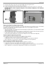
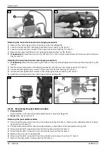
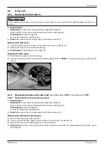
Removing the joystick module and LCD module
1) Remove the control panel and take out the retaining plate (see Page 32).
2) Loosen and remove the 2 screws between the housing and joystick module (see Fig. 45, item 1).
3) Pull the joystick module upward out of the housing (see Fig. 45, item 2).
4) Loosen and remove the screw between the housing and LCD module (see Fig. 45, item 3).
5) Pull the LCD module forward out of the housing (see Fig. 45, item 4).
INFORMATION: In doing so, carefully thread the control panel cable through the opening in the centre
JAOC@CJPNDIBN@@DB{ÁÂxDO@HÂ{
Installing the joystick module and LCD module
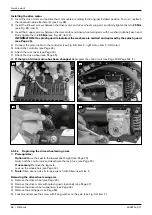
1) Insert the LCD module into the housing from the front (see Fig. 45, item 4).
INFORMATION: In doing so, carefully thread the control panel cable through the opening in the centre
JAOC@CJPNDIBN@@DB{ÁÂxDO@HÂ{
2) IN@MOOC@N>M@R=@OR@@IOC@CJPNDIB<I?HJ?PG@<I?uMHGTODBCO@IDOOJ0.75 Nm (see Fig. 45, item 3).
3) Carefully set the joystick module into the housing and onto the LCD module from above (see Fig. 45, item 2).
4) IN@MOOC@¿N>M@RN=@OR@@IOC@CJPNDIB<I?EJTNOD>FHJ?PG@<I?uMHGTODBCO@IOC@HOJ0.75 Nm (see Fig. 45,
item 1).
5) Attach the retaining plate and install the control panel (see Page 32).
6) Recalibrate the joystick.
Recalibrating the joystick
1) Switch the wheelchair control device off.
2) Connect the programming dongle, switch the wheelchair back on again and start on-board programming (see
Page 146).
INFORMATION: On-board programming is not activated on delivery of the control device. In this case,
first carry out PC programming, back up the parameters and activate on-board programming when
needed.
3) @G@>OOC@TNO@HH@IP=TN>MJGGDIBEJTNOD>FAMJIO=<>F<I?>JIuMHTJPMN@G@>ODJI=THJQDIBOC@EJTNOD>FOJ
the right.
4) @G@>OOC@JTNOD>F><GD={H@IP=TN>MJGGDIBEJTNOD>FAMJIO=<>F<I?>JIuMHTJPMN@G@>ODJI=THJQDIBOC@EJT-
stick to the right.
5) The procedure is carried out automatically. Follow the instructions on the LCD monitor. Values for forward/rever-
se and left/right axes are displayed. A symbol appears next to each value (X or checkmark):
X: the axis value is outside the permitted calibration range for this direction.
Checkmark: the axis value is within the permitted calibration range for this direction.
6) @v@>OOC@EJTNOD>FDIOC@>JMM@NKJI?DIB?DM@>ODJIPIODG=JOCQ<GP@N<M@DIOC@K@MHDOO@?M<IB@{@K@<OAJM<GGÁ
directions.
7) The LCD monitor shows when the calibration has been completed successfully. The display then returns to the
system menu.
8) End on-board programming and remove the programming dongle.
INFORMATION: If you have activated on-board programming, deactivate it again using PC program-
ming and back up the parameters.
Summary of Contents for 490E75 Series
Page 1: ...490E75 0_C Service manual...
Page 38: ...Service work 490E75 0_C 38 Ottobock 57 58 59 60 61 62 63...
Page 41: ...Service work 490E75 0_C Ottobock 41 70 71 72 73 74 tt 75 76...
Page 55: ...Service work 490E75 0_C Ottobock 55 103 104 105 106 107 108 109 110...
Page 108: ...Service work 490E75 0_C 108 Ottobock 227 228 229 t 230 231 232...
Page 112: ...Service work 490E75 0_C 112 Ottobock 237 238 239 240 241...
Page 143: ...R Net wheelchair control 490E75 0_C Ottobock 143 Seat module pin assignment 287...
Page 161: ...490E75 0_C Ottobock 161...
Page 162: ...490E75 0_C 162 Ottobock...

