Service work
490E75=0_C
42 | Ottobock
4.8.13 Replacing the mo-Vis joystick control on the tray
f
Prerequisites:
Switch off the control device and deactivate the main fuse (see Page 15).
f
Tools: Allen wrench size 4, 5
Removing the mo-Vis joystick control on the tray
1) INFORMATION: Note the installed position of the cables and cable attachments.
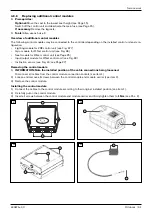
Disconnect the cable of the mo-Vis controller from the cable extension (see Fig. 75, item 5). Remove the cable
attachments if necessary.
2) Loosen and remove the tray, and set it aside.
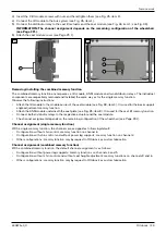
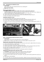
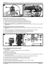
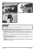
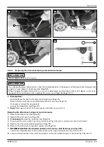
3) Loosen and remove the 2 screws between the holder and tray (see Fig. 77/78, item 1).
4) Remove the holder with the joystick (see Fig. 77/78, item 2).
zC@M@DN<KG<O@<I?>JHKM@NNDJINKMDIB=@OR@@IOC@CJG?@M<I?OM<TN@@DB{ÄÄÄÅx
DO@HÀ{<A@GTNOJM@OC@N@>JHKJI@IONOJB@OC@MRDOCOC@CJG?@M{
5) Loosen the thumb screw of the holder and take off the joystick with the mo-Vis controller (see Fig. 77/78, item 4).
Installing the mo-Vis joystick control on the tray
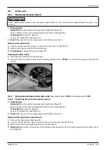
1) Set the holder onto the tray from below.
zIN@MOOC@KG<O@<I?>JHKM@NNDJINKMDIB=@OR@@IOC@CJG?@M<I?OM<TN@@DB{ÄÄÄÅx
DO@HÀ{
2) Insert and hand-tighten the 2 screws between the holder and tray (see Fig. 77/78, item 1).
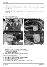
3) GD?@OC@EJTNOD>FDIOJOC@CJG?@M<I?uMHGTODBCO@I<GGN>M@RNJAOC@CJG?@M{
zAI@>@NN<MTxAJG?OC@CJG?@M?JRIuMNO{?EPNOOC@C@DBCOJAOC@EJTNOD>FRDOCOC@OCPH=
N>M@RN@@DB{ÄÄxDO@HÁ<I?OC@>@IOM@KJNDODJIRDOCOC@>G<HKDIBN>M@Rx<NI@@?@?N@@DB{ÄÄx
DO@HÂ{
4) Attach the tray to the wheelchair.
5) Attach the mo-Vis controller under the seat according to the original installed position.
6) Position and connect the cables according to their original installed position. Reattach the loosened cable at-
tachments in doing so.
INFORMATION: Make sure that cables cannot get stretched, pinched or caught when the wheelchair is
operated.
7) @MDATOC@API>ODJI<GDOTJAOC@CJG?@M<I?OC@uMHuOJAOC@EJTNOD>F{
8) If necessary: Recalibrate the joystick.
77
78
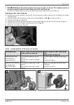
Recalibrating the joystick
INFORMATION
The described calibration applies for a mo-Vis joystick control connected to a separate display and connection
module. The calibration is started with the help of the display module.
If the mo-Vis joystick control is connected directly to the bus system, contact the manufacturer for additional infor-
mation regarding the calibration.
1) Open the "Settings" menu on the display module (gear wheel symbol).
2) @G@>OOC@ÞMJBM<HHDIBÞH@IPRDOCOC@PK?JRI<MMJRN<I?>JIuMHTJPMN@G@>ODJIRDOCOC@MDBCO<MMJR{
Summary of Contents for 490E75 Series
Page 1: ...490E75 0_C Service manual...
Page 38: ...Service work 490E75 0_C 38 Ottobock 57 58 59 60 61 62 63...
Page 41: ...Service work 490E75 0_C Ottobock 41 70 71 72 73 74 tt 75 76...
Page 55: ...Service work 490E75 0_C Ottobock 55 103 104 105 106 107 108 109 110...
Page 108: ...Service work 490E75 0_C 108 Ottobock 227 228 229 t 230 231 232...
Page 112: ...Service work 490E75 0_C 112 Ottobock 237 238 239 240 241...
Page 143: ...R Net wheelchair control 490E75 0_C Ottobock 143 Seat module pin assignment 287...
Page 161: ...490E75 0_C Ottobock 161...
Page 162: ...490E75 0_C 162 Ottobock...


