Service work
490E75=0_C
Ottobock | 47
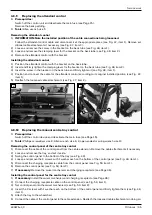
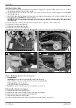
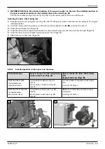
INFORMATION: A grounding cable with grounding washer is also mounted on one of the two drive
RC@@GNRDIB<MHN{OO<>COCDNBMJPI?DIBOJB@OC@MRDOCOC@N>M@R>JII@>ODJIN@@DB{ÅÂxDO@HÁ{M-
M<IB@OC@BMJPI?DIB><=G@NP>COC<ODO><I?M<B<B<DINOOC@vJJM{
3) Carefully guide the drive wheel swing arm upwards.
4) IN@MOOC@N>M@RRDOC¾R<NC@M=@OR@@IOC@NPNK@INDJI<I??MDQ@PIDO=M<>F@O<I?uMHGTODBCO@IDOOJ25 Nm (see
Fig. 84/85, item 1).
5) Attach the drive wheel (see Page 45).
6) Adjust the drive wheel suspension equally on both sides (see Page 72).
84
85
4.9.2.3 Replacing the drive motors
INFORMATION
Always replace drive motors in pairs.
INFORMATION
If you change the type of drive motors, check the installed position of the spacers on the drive wheel swing arm and
suspension and replace if necessary (see Page 49).
When changing the type of drive motors, a new set of parameters must be input in the control unit. In this case,
reprogram the control unit after replacing the motors (see Page 134/Page 141 ff.).
f
Prerequisites:
Optional: Move the seat to the lowest seat height (see Page 15).
Switch off the control unit and deactivate the main fuse (see Page 15).
If necessary: Remove the legrests.
Jack up the wheelchair (see Page 14).
f
Tools: Allen wrench size 6; torque wrench with Allen insert size 6
Removing the drive motor
1) Remove the drive wheel (see Page 45).
2) Remove the rear cover (see Page 19).
3) If necessary: Remove the controller (see Page 24).
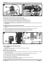
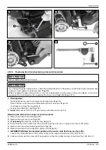
4) Disconnect the motor cable from the controller (see Fig. 86, item 1: right motor, item 2: left motor).
5) Loosen and remove the 2 upper screws between the drive motor and drive wheel swing arm with 1 washer (op-
tional) each (see Fig. 73, item 1).
INFORMATION: If a splash guard is installed, there are no washers under the screws. In this case, re-
HJQ@OC@NKG<NCBP<M?<AO@MGJJN@IDIBOC@N>M@RNN@@PageÁÂ{
6) Loosen the cable attachment on the motor cable (see Fig. 88).
7) Loosen and remove the 2 lower screws between the drive motor and drive wheel swing arm (see Fig. 89, item 1).
8) INFORMATION: Note the installed position of the motor cable.
Remove the drive motor with the motor cable. Remove additional cable attachments if necessary.
Summary of Contents for 490E75 Series
Page 1: ...490E75 0_C Service manual...
Page 38: ...Service work 490E75 0_C 38 Ottobock 57 58 59 60 61 62 63...
Page 41: ...Service work 490E75 0_C Ottobock 41 70 71 72 73 74 tt 75 76...
Page 55: ...Service work 490E75 0_C Ottobock 55 103 104 105 106 107 108 109 110...
Page 108: ...Service work 490E75 0_C 108 Ottobock 227 228 229 t 230 231 232...
Page 112: ...Service work 490E75 0_C 112 Ottobock 237 238 239 240 241...
Page 143: ...R Net wheelchair control 490E75 0_C Ottobock 143 Seat module pin assignment 287...
Page 161: ...490E75 0_C Ottobock 161...
Page 162: ...490E75 0_C 162 Ottobock...


