Service work
490E75=0_C
Ottobock | 77
Replacing the rear seat height adapter
CAUTION
Improper lifting
Crushing, pinching, blows due to failure to observe safety instructions, product damage
f
The seat of the power wheelchair is very heavy. Ensure ergonomically correct lifting. Use sufficiently large hoi-
sting devices and perform this work with a helper.
f
Take care to prevent crushing of limbs while raising or lowering the seat.
f
Before raising or lowering the seat, disconnect all cable connections and cable attachments between the seat
and mobility base. Make sure that no cables, cable attachments or other components are torn off, crushed or
damaged while raising or lowering the seat.
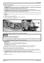
1) Fold up the seat (see Page 16).
2) Remove the battery cover (see Page 17).
3) Remove the rear cover (see Fig. 150, item 1; see Page 19).
4) INFORMATION: Note the installed position of the cables and cable attachments.
Disconnect all cables and cable attachments between the seat and mobility base (see Fig. 160, item 2). Carefully
pull all seat cables out of the mobility base (see Fig. 160, item 3).
5) Carefully fold down the seat (see Page 16) and set it down on the support bolts. Do not tighten the support
bolts.
6) INFORMATION: Take note of the installed position of the ratchet bolt with seat bracket spacer, com-
pression spring and nut.
On the left side of the seat frame, loosen and remove the ratchet bolt with seat bracket spacer, compression
spring and nut (see Fig. 161, item 1).
7) WARNING! Severe injuries due to pinching, crushing if the seat falls down. Secure the seat against fal-
ling down with the active support of a helper.
zJO@OC@DINO<GG@?KJNDODJIJAOC@N>M@RRDOC=PNCDIBxN@<O=M<>F@ONK<>@MJKODJI<G
and nut. Depending on the size of the mobility base, there is no seat bracket spacer installed on this
screw connection.
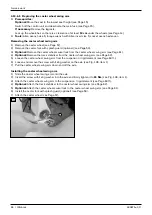
Loosen and remove the screw with bushing, seat bracket spacer (optional) and nut on both sides (see Fig. 161,
item 2).
8) Carefully pull the seat upwards off the mobility base and set it safely aside with the support of a helper.
9) INFORMATION: Note the installed position of the seat height adapter. The alignment and type of the
seat height adapter depends on the size of the mobility base and the drive unit type.
Loosen and remove the 2 screws on the seat height adapter (see Fig. 161, item 3).
10) Replace the seat height adapter and move it to the desired position.
NOTICE! Damage to the product due to adjustments outside the permissible ranges. Only set seat height
<?<KO@MKJNDODJINRCD>C<M@GDNO@?DIOC@O<=G@NCJRDIBK@MHDNND=G@>JH=DI<ODJINN@@PageÄÅ{J-
sition the left and right seat height adapters evenly using the applied markings.
11) IN@MOOC@¿N>M@RNDIOJOC@N@<OC@DBCO<?<KO@M<I?uMHGTODBCO@IOC@HOJ25 Nm (see Fig. 161, item 3).
12) With the support of a helper, set the seat onto the seat height adapters from above.
13) Insert the screw with bushing, seat bracket spacer (optional) and nut on both sides according to its original ins-
talled position (see Fig. 161, item 2).
INFORMATION: Depending on the size of the mobility base, no seat bracket spacer is installed on this
screw connection.
14) On the left side of the seat frame, insert the ratchet bolt with seat bracket spacer, compression spring and nut
<>>JM?DIBOJDONJMDBDI<GDINO<GG@?KJNDODJI<I?uMHGTODBCO@IN@@DB{161, item 1).
15) WARNING! Severe injuries due to pinching, crushing if the seat falls down. Verify correct functionality
of the ratchet bolt.
Carefully fold up the seat (see Page¾Ã{C<F@OC@N@<OOJQ@MDATOC<ODODNuMHGTGJ>F@?{
16) Install all cable connections and cable attachments according to the original installed position (see Fig. 160,
item 2/3).
17) Attach the rear cover (see Page 19).
18) Attach the battery cover (see Page 17).
19) Fold down the seat (see Page 16).
20) Check all seat functions.
Summary of Contents for 490E75 Series
Page 1: ...490E75 0_C Service manual...
Page 38: ...Service work 490E75 0_C 38 Ottobock 57 58 59 60 61 62 63...
Page 41: ...Service work 490E75 0_C Ottobock 41 70 71 72 73 74 tt 75 76...
Page 55: ...Service work 490E75 0_C Ottobock 55 103 104 105 106 107 108 109 110...
Page 108: ...Service work 490E75 0_C 108 Ottobock 227 228 229 t 230 231 232...
Page 112: ...Service work 490E75 0_C 112 Ottobock 237 238 239 240 241...
Page 143: ...R Net wheelchair control 490E75 0_C Ottobock 143 Seat module pin assignment 287...
Page 161: ...490E75 0_C Ottobock 161...
Page 162: ...490E75 0_C 162 Ottobock...

