Service work
490E75=0_C
Ottobock | 81
4.13.7 Adjusting the centre of gravity (VAS seat with module for combination of seat height adjust-
ment and seat tilt)
WARNING
Shifting the centre of gravity
Severe injuries due to the power wheelchair tipping over and falling
f
Only choose positions that are permissible for the new configuration. Contact Ottobock Customer Service for
more information. Have the serial number of the power wheelchair ready. It is used to determine the permissi-
ble positions.
f
Prior to initial use, test how changes in the centre of gravity affect the behaviour of the power wheelchair on
inclines, slopes, side hills or when crossing obstacles with the secure support of an attendant.
CAUTION
Failure to observe installation instructions
Pinching, crushing due to falling parts
f
The seat and its individual parts have a substantial weight. Secure the parts against falling before loosening
them.
f
Prerequisites:
Optional: Move the seat to the lowest seat height (see Page 15).
Switch off the control device and deactivate the main fuse (see Page 15).
If necessary: remove the leg supports.
f
Tools: Allen wrench size 6; torque wrench with Allen insert size 6
Dependencies
The seat‘s centre of gravity can be adjusted by sliding the seat frame and combination seat height and seat tilt adjust-
ment module relative to the mobility base. Among other things, the permissible centre of gravity depends on:
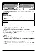
• Type and size of the mobility base (front-wheel drive FWD see Fig. 169, mid-wheel drive MWD see Fig. 170,
rear-wheel drive RWD see Fig. 171)
• Seat depth
• User weight
Adjusting the centre of gravity
1) Check the frame measurement of the VAS seat.
INFORMATION: The distance from the front seat bracket to the front edge of the seat must be 110 mm
N@@DB{¾ÃÅxDO@H¾{AI@>@NN<MTx>JMM@>OOC@AM<H@H@<NPM@H@IOOJ¾¾½HH=TNGD?DIBOC@N@<O=<MN
JIOC@N@<O=M<>F@ON<I?uMHGTM@}ODBCO@IDIBOC@N>M@RN{
2) Loosen and remove the 4 screws between the mobility base and module on both sides (see item 2).
3) GD?@OC@HJ?PG@OJ<KJNDODJIOC<ODNK@MHDNND=G@AJMOC@I@R>JIuBPM<ODJI{
4) IN@MOOC@ÁN>M@RN=@OR@@IOC@HJ=DGDOT=<N@<I?HJ?PG@JI=JOCND?@Nx<I?uMHGTODBCO@IOC@HOJ25 Nm (see
item 2).
5) Loosen and remove the 4 screws between the seat frame and module on both sides (see item 3).
6) GD?@OC@N@<OAM<H@OJ<KJNDODJIOC<ODNK@MHDNND=G@AJMOC@I@R>JIuBPM<ODJI{
7) IN@MOOC@ÁN>M@RN=@OR@@IOC@N@<OAM<H@<I?HJ?PG@JI=JOCND?@Nx<I?uMHGTODBCO@IOC@HOJ25 Nm (see
item 3).
8) Check the control measurement of the seat.
INFORMATION:
The control measurement is measured from the front edge of the front seat height ad-
apter to the front edge of the seat, and varies depending on the configuration.
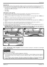
168
169
Summary of Contents for 490E75 Series
Page 1: ...490E75 0_C Service manual...
Page 38: ...Service work 490E75 0_C 38 Ottobock 57 58 59 60 61 62 63...
Page 41: ...Service work 490E75 0_C Ottobock 41 70 71 72 73 74 tt 75 76...
Page 55: ...Service work 490E75 0_C Ottobock 55 103 104 105 106 107 108 109 110...
Page 108: ...Service work 490E75 0_C 108 Ottobock 227 228 229 t 230 231 232...
Page 112: ...Service work 490E75 0_C 112 Ottobock 237 238 239 240 241...
Page 143: ...R Net wheelchair control 490E75 0_C Ottobock 143 Seat module pin assignment 287...
Page 161: ...490E75 0_C Ottobock 161...
Page 162: ...490E75 0_C 162 Ottobock...


