Service work
490E75=0_C
94 | Ottobock
4.14.6 Removing/installing the power back angle adjustment (standard seat)
INFORMATION
Power back angle adjustment (standard seat) requires a special back frame and bearing plates, and is repla-
ced together with these (see Page 92). The back angle adjustment actuator can be replaced separately (see
Page 94).
When changing the back angle adjustment type (mechanical or power back angle adjustment), additional adjust-
ments such as additional control modules, new cabling or reprogramming the control unit may be required. Con-
tact your national Ottobock team before changing the back angle adjustment type.
f
Prerequisites:
Switch off the control unit and deactivate the main fuse (see Page 15).
Remove the seat cushion and back padding.
f
Tools: Allen wrench size 6; open-ended or ring wrench size 13; torque wrench with Allen insert size 6
Removing the power back angle adjustment (standard seat)
1) Remove the actuator for the power back angle adjustment (see Page 94) and fold the back forwards onto the
seat.
2) If necessary: Remove and replace the back (see Page 92).
3) Optional: Install the manual back angle adjustment (see Page 95).
Installing the power back angle adjustment (standard seat)
1) Optional: Remove the manual back angle adjustment (see Page 95).
2) Install the back for the power back angle adjustment (see Page 92).
3) Install the actuator for the power back angle adjustment (see Page 94).
4.14.7 Replacing the actuator for the power back angle adjustment (standard seat)
f
Prerequisites:
Switch off the control unit and deactivate the main fuse (see Page 15).
f
Tools: Allen wrench size 4; torque wrench with Allen insert size 4
Removing the power back angle adjustment actuator (standard seat)
1) INFORMATION: Note the installed position of the cable connections being loosened. The actuator cable
DN>JII@>O@?OJOC@N@<OHJ?PG@JMOC@>JIOMJGG@M?@K@I?DIBJIOC@>JIuBPM<ODJI{
Follow the actuator cable and disconnect it from the seat module/controller. To do so, remove the cover from the
seat module / controller (see Page 25/Page 19).
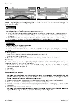
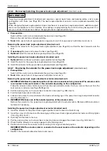
2) Pull the retaining claw on the lower back connection tube (see Fig. 198, item 1).
3) Fold the back forwards onto the seat.
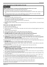
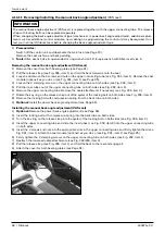
4) Loosen and remove the screw between the back and bearing eye of the power back angle adjustment actuator
(see Fig. 199, item 1).
5) INFORMATION: Take note of the installed position of the actuator cable.
Remove the actuator for the power back angle adjustment with the actuator cable. Remove additional cable at-
tachments if necessary.
Installing the power back angle adjustment actuator (standard seat)
1) IN@MOOC@<>OP<OJMAJMOC@KJR@M=<>F<IBG@<?EPNOH@IODIOJOC@=<>F<I?CJG?DOuMHGT{
2) IN@MOOC@N>M@RDIOJOC@=<>F<I?OC@=@<MDIB@T@JAOC@KJR@M=<>F<IBG@<?EPNOH@IO<>OP<OJM<I?uMHGTODBCO@I
it (see Fig. 199, item 1).
3) Carefully fold the back to the rear.
4) Pull the retaining claw on the lower back connecting tube and engage the actuator (see Fig. 198, item 1).
5) Check that the actuator is securely engaged in the retaining claw.
6) Position and connect the actuator cable according to its original installed position.
INFORMATION: The actuator cable is connected to the seat module or the controller depending on the
>JIuBPM<ODJI{
7) Reattach the loosened cable attachments and covers.
Summary of Contents for 490E75 Series
Page 1: ...490E75 0_C Service manual...
Page 38: ...Service work 490E75 0_C 38 Ottobock 57 58 59 60 61 62 63...
Page 41: ...Service work 490E75 0_C Ottobock 41 70 71 72 73 74 tt 75 76...
Page 55: ...Service work 490E75 0_C Ottobock 55 103 104 105 106 107 108 109 110...
Page 108: ...Service work 490E75 0_C 108 Ottobock 227 228 229 t 230 231 232...
Page 112: ...Service work 490E75 0_C 112 Ottobock 237 238 239 240 241...
Page 143: ...R Net wheelchair control 490E75 0_C Ottobock 143 Seat module pin assignment 287...
Page 161: ...490E75 0_C Ottobock 161...
Page 162: ...490E75 0_C 162 Ottobock...


